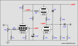
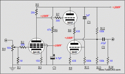
Why don't you strap the 6AU6 in triode mode? Too much gain/noise/distortion in pentode if you cannot regulate the screen supply IMHO.
SY
Tubes one and two (both slight noise)International Brand(Japan)
Tubes 3 and 4 are National Brand (USSR)
Tube 1 Pin 5 75 volts, pin 6 85 volts, pin 7 1.343 volts
Tube 2 pin 5 75 volts, pin 6 85 volts, pin 7 1.355 volts
Tube 3 pin 5 109.5 volts pin 6 111 volts pin 7 .929 volts
Tube 4 pin 5 102 volts pin 6 102 volts pin 7 1.031 volts
Tubes 1 and 2 have some noise
Tube 3 is dead quiet
Tube 4 has some noise noise moves with tube
Quote:
Why don't you strap the 6AU6 in triode mode? Too much gain/noise/distortion in pentode if you cannot regulate the screen supply IMHO.
Won't this change the sonics quite a bit? What suggestions do you have for doing this?
Why don't you strap the 6AU6 in triode mode? Too much gain/noise/distortion in pentode if you cannot regulate the screen supply IMHO.
Won't this change the sonics quite a bit? What suggestions do you have for doing this?
Is there a possible pattern here? Less plate and screen voltage on tubes 1, 2, and 4 than what tube 3 has on it. Would this mean more noise?
If tube n.° 3 has higher plate/screen voltages, it means that it doesn't conduct so much current like other tubes, and probably it's old/gassy/exhaust.
The change in sonics by triode connecting the 6au6 will have to be determined by your ears 😉
Try to connect the screen to the plate, removing it's resistor and capacitor that I see on the schematics. But you probably have to change the operating point of the tube. If you want to recalculate it, you'll have to find curves for the 6AU6 in triode mode, and choose a plate and cathode resistor combo that will give good linearity for that B+ voltage.
Giaime
All 4 tubes were never used before I put them into circuit and they tested good on my tester (Mercury 204).
All 4 tubes were never used before I put them into circuit and they tested good on my tester (Mercury 204).
burnedfingers said:Giaime
All 4 tubes were never used before I put them into circuit and they tested good on my tester (Mercury 204).
So tube n.° 3 is simply sightly out of spec, it's common for tubes even now in box.
Do you remember the new-in-box 0D3 you sent me? Well, it ignites at 155V instead if 150 😉
Actually, that spread in numbers isn't surprising- the ratio of screen to plate current in small signal pentodes is not tightly specified.
I did some playing with the 6AU6 based unit and found that I need to change the tube socket with one that will allow the used of the tube shield. This seems to take care of most of the noise on the tubes 1 and 2.
About tube shields... I tried one on the first tube of my phono pre, and it didn't make any difference even with the PT at 5 centimeters from the tube... of course the shield was connected to ground.
But the microphonic noise became worse... more like a bell.
But the microphonic noise became worse... more like a bell.
Just making a guess here...maybe it depends on the tube make up inside. It helped the international brand tube but did nothing for the other two.
As soon as I slid the cover on the noise went away like magic.
As soon as I slid the cover on the noise went away like magic.
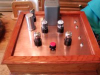
A picture of my Aikido that I am almost done with. It is pale compared to the work of some more gifted people here but still a work of love.
PS..
I need a piece of copper round stock in which to turn a nice volume control knob. It would be nice if I could find a piece of 3/4-1.5 inch diameter. Willing to buy.
PS..
I need a piece of copper round stock in which to turn a nice volume control knob. It would be nice if I could find a piece of 3/4-1.5 inch diameter. Willing to buy.
Attachments
Well, it's far nicer than the plans I have for mine 😀 My best compliments!
Did you done that wonderful wood work for the base?
And that PT looks like salvaged... from where?
Did you done that wonderful wood work for the base?
And that PT looks like salvaged... from where?
Lovely piece of work!
I notice that the input jacks are insulated from the chassis. Where do you put your ground?
For your knob stock, Mcmaster-Carr. Part number 9100K181 is 1" diameter, 12" long. $33.
I notice that the input jacks are insulated from the chassis. Where do you put your ground?
For your knob stock, Mcmaster-Carr. Part number 9100K181 is 1" diameter, 12" long. $33.
SY
The ground is a piece of 12ga solid wire that I soldered to the underside of the copper plate . It runs up the middle to permit a ladder type connection scheme.
Everything on this is old and recycled with exception of one of the sockets and the wood base. Granted the resistors are new along with several caps. The transformer I purchased from a friend and it is out of a piece of test equipment I believe. It has a Chicago Standard name on it.
I still need to float the VC from the chassis and I will need to find some different fibre or plastic washers for that. Also needed is a insulator for the 4 section capacitor and a nice looking VC knob.
It is very nice sounding it is delicate yet has authority. The 5692 as input tubes are quite nice and provide a night and day difference over the Sylvania Chrome tops. I haven't tried any other tubes. The back tubes are NOS GE.
The wood base was made for me by a cabinet maker in return for me fixing an old radio for him. Unfortunately, the only thing I can do with wood is make unusable pieces out of it.
For my 6SN7 input tube I used 864 ohms (432 X 2) ea for my cathode resistors with puts me at 5mA. For my cathode follower tube (second tube) I used what I had (330 ohm) about 8mA. I need to bump it up to 10mA.
For the heck of it can I try a 6SL7 as my input tube? I know I don't need the gain but I want to find out how it will sound.
For the heck of it can I try a 6SL7 as my input tube? I know I don't need the gain but I want to find out how it will sound.
- Status
- Not open for further replies.
- Home
- Amplifiers
- Tubes / Valves
- Making sense of the Aikido calculations?