JojoD
use the values as in JB's 6n19>5687 linestage to start
http://tubecad.com/2005/January/blog0030.htm
the ecc82 is similar enough to 5687
ecc88 is also similar to 6n1p
this is better than an all ecc88 linestage
which can sound very exciting
just remember to wire the heaters correctly
it will sound very good
dave dove
dave dove said:JojoD
use the values as in JB's 6n19>5687 linestage to start
http://tubecad.com/2005/January/blog0030.htm
the ecc82 is similar enough to 5687
ecc88 is also similar to 6n1p
this is better than an all ecc88 linestage
which can sound very exciting
just remember to wire the heaters correctly
it will sound very good
dave dove
dave,
thanks for the heads up.
could you please elaborate on the "correct" heater wiring, I don't want to end up damaging my tubes.
any warnings/cautions are extremely welcome.
if you connect ecc82/12at7 heaters to pins 4+5
you will need a 12V heater supply
for 6V you can however tie pins 4+5 together
and use pin 9 as the second heater connection
ecc88/6922 has only 6V heaters
pins 4+5
the first time i used ecc99 i connected 6.3V to pins 4+5
took me two days to work out why no sound....
dave dove
you will need a 12V heater supply
for 6V you can however tie pins 4+5 together
and use pin 9 as the second heater connection
ecc88/6922 has only 6V heaters
pins 4+5
the first time i used ecc99 i connected 6.3V to pins 4+5
took me two days to work out why no sound....
dave dove
dave dove said:if you connect ecc82/12at7 heaters to pins 4+5
you will need a 12V heater supply
for 6V you can however tie pins 4+5 together
and use pin 9 as the second heater connection
ecc88/6922 has only 6V heaters
pins 4+5
the first time i used ecc99 i connected 6.3V to pins 4+5
took me two days to work out why no sound....
dave dove
thanks for reminding me, i got that thing all memorized now. so a single 6.3V for 2-6922 and 2-12atz would be ok and lifted above ground about half the b+. whew!
thanks!
Hi everyone. I've been following this thread with great interest. Has anyone considered using 5965's? Is there any reason why I couldn't use four 5965's.I have a few matched pairs of these (NOS GE) and I'm currently using two pairs in my Papworth preamp in place of the ECC81's. I like the sound they give. Like one or two others, I tend to get a bit lost with the technicalities so any help is appreciated. Si.
harwoodspark
I will throw in my .02 if its ok. As one that also likes tubes with a little more gain I can tell you that I've built several other Aikido line stages with high mU tubes. The problem is going to be too much gain. This will result in some noise/hiss and the ability to clip ones amp by just breathing on the volume control. The more is better attitude is great if one is going to race their supercharged Z-28 Camaro down the strip but I can assure you that the mU or amplification factor of the 5965 is more than you will end up being happy with.
May I suggest building an Aikido with 6SN7's for both the 1st and second tube locations or possibly an Aikido with 6FQ7 as a first tube and 5687 as a second tube? To make it simple I would highly suggest a tube with an mU around 20 as this will give MORE than ample gain without the associated problems caused by the extra gain.
You can sub 6SN7's for the 12SN7's. Check out the photo of my completed 6SN7 AIkido project in the photo gallery, post #880
Attachments
6SN7's for Aikido.
Well there you go then, 6SN7's it is. I have some NOS of these as well. Russian made but so are the KT66's in my amps and they sound fine. By the way, what is the gain of the 5965?
I'm off to the picture gallery now. Si.
Well there you go then, 6SN7's it is. I have some NOS of these as well. Russian made but so are the KT66's in my amps and they sound fine. By the way, what is the gain of the 5965?
I'm off to the picture gallery now. Si.
Hey Burnedfiger, since this is a thread on Aikido calculations could I ask how you came up with the resistor values for the first stage of your pre-amp using 12SN7 in both stages? Why is it that the first stage only draws 5mA and the second stage draws 10mA? Did I miss something here? 😕
For everyone else here, I have a pair of 12BH7 and a pair of 5687 which I was planning to use. My question is which tube will give the flavor of the pre-amp, the first or the second tube? In my application, should I use the 5687 in the first or second stage? I think I may have a few 12AU7 lying around somewhere. Should I use them instead?
TIA...
Aikido calcs.
Hi RockysDad. I don't think burnedfingers came up with any calculated figures for the Aikido circuit you see in post 86.This was lifted straight from John Broskie's Guide to Tube Circuit Analysis and Design (8th November 2004), the man responsible for the Aikido design. Si.
Hi RockysDad. I don't think burnedfingers came up with any calculated figures for the Aikido circuit you see in post 86.This was lifted straight from John Broskie's Guide to Tube Circuit Analysis and Design (8th November 2004), the man responsible for the Aikido design. Si.
harwoodspark is correct. The schematic was lifted straight from John Broskie's Guide to Tube Circuit Analysis and Design (8th November 2004), the man responsible for the Aikido design.
If you check his designs I believe you will find that the first stage usually runs at 5mA and the second stage at 10mA with the exception of the 12AU7 and pentode designs. The pentode design and the 12Au7 single first tube design run at around 8mA.
If you check his designs I believe you will find that the first stage usually runs at 5mA and the second stage at 10mA with the exception of the 12AU7 and pentode designs. The pentode design and the 12Au7 single first tube design run at around 8mA.
Quote:
For everyone else here, I have a pair of 12BH7 and a pair of 5687 which I was planning to use. My question is which tube will give the flavor of the pre-amp, the first or the second tube? In my application, should I use the 5687 in the first or second stage? I think I may have a few 12AU7 lying around somewhere. Should I use them instead?
Personally, I would use the 12bH7 for the first stage and the 5687 for the second stage. Better yet use 6fq7 or 12fq7 as the "flavor tube".
Keep the 12AU7's in the drawer.
quote:
Originally posted by dhaen
But isn't that a mincer they are going in?
Best thing for them.
One solution for 12Au7's
Originally posted by dhaen
But isn't that a mincer they are going in?
Best thing for them.
One solution for 12Au7's
burnedfingers said:Quote:
Personally, I would use the 12bH7 for the first stage and the 5687 for the second stage. Better yet use 6fq7 or 12fq7 as the "flavor tube".
Is this the first or second section?
Keep the 12AU7's in the drawer.
Humm... That bad, huh.....
Guys I need help in confirmation, this is my plan for my all 12SN7 Aikido.
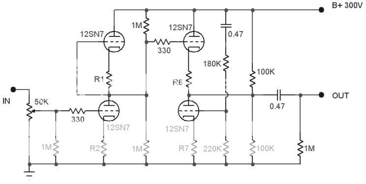
1. With the 300V, I know that if I will run the output section at 10mA that I need to use about 330 ohms for R6 and R7 (found on the first page of this thread).
2. If the usual input section is run at 5mA current, how do I calculate for R1 and R2?
3. Is the 180k and 220K just ok? I mean a combination of 39K and 47K is also valid but should I use smaller value or bigger value? I did used the 1/mu+1/2 formula.
4. How many volts must I lift the heaters to ground?
I plan to use regulated DC for the heaters.
Appreciate any help,
JojoD
Yes.Are the 330 ohms on the grids of the tubes just serves as grid stoppers?
The 12SN7 is the same as 6SN7 I suppose in that respect. 90V is max up and down (limit). If your B+ = 300 than your top cathode will site at (+-) 150VDC. You want both the bottom and top triode to be within spec.How many volts must I lift the heaters to ground?
So if you aim for say 80VDC...
Top triode=sits at 150 the potential difference (between 150 and 80)= 70 means within spec..
the bottom one sits at say 3V. The potential difference between 80 and 3 V =77 means within spec.
If the calculations have been done well..and the ratio is good..sounds good...I don't think you need a lot of current ..in other words don't go much lower in values.Is the 180k and 220K just ok?
Hi Bas,
Well if those 330 ohms are just there for grid stoppers then there shouldn't be any problem if I use 1K since I have a bunch of those allen bradley resistors in 1/2 watt.
The ratio is good as per formula, so I would use the 180K-220K combo instead of the 39K-47K combo then.
Can you please shed some light as to the values for R1 and R2.
Thanks for the answers, helpful indeed.
JojoD
Hi JojoD,Can you please shed some light as to the values for R1 and R2.
I'm afraid if I try to explain, everyone will see how little I know... I usually look at other schematics to get ballpark resistors values. Or try to find recommendations from experienced folks...that are given on forums from time to time....Or I just try and see...put in say 1k and then measure...to see how much current is flowing..how it sounds...and calculate the dissapation....etc..etc.
Regards,
Bas
- Status
- Not open for further replies.
- Home
- Amplifiers
- Tubes / Valves
- Making sense of the Aikido calculations?