So, how would you layout/spec a ADUM type isolator/power injector pcb, multiple layers expected.So you like the emperors news clothes.... anecdotal hearsay does not count.....
This can be your chance to contribute something material to this discussion.
Dan.
My evidence, which I stated before, is that ADuM Isolator increases THD of a "digital" signal. This is proof that, on my equipment, bad USB signal has a negative effect. Just the fact that it has an effect proves that there is some relationship there. Just because (according to you) I don't understand exactly why and how it is happening doesn't mean it isn't happening.
It is interesting that you don't give any credence at all to the idea that forum members; subjective tests have at least a bit of validity. If you were to tell me that X amp has tighter bass and bloomy mids and amp Y has a sibilant treble I wouldn't expect someone would say "you don't know what you are talking about".
Second time this question has been asked how do you determine the THD of a digital signal.......
Again you need to provide proof, real proof, like Max does for all his esoteric beliefs and claims, we are at the extreme edge of audio silliness with some of this stuff, so proof needs to be provided.
I'm afraid they are both. They are digital signals riding an analog medium, in this case a wire. If they were digital they would have no overshoot or ringing, no high frequency hash from whatever source, and infinite slew rate, but they do.
How much time do you spend doing digital signal integrity or digital/analogue layout... Please try and understand the reality, digital signals are treated as digital signals, NOT analogue, they are made up of multiple harmonics from a fundamental clock signal, overshoot and ringing are aspects of digital signals, we always treat them as digital signals and use digital signal techniques to solve ringing and overshoot... They are digital signals so you use techniques and engineering practice designed for digital signals....
So define a digital signals THD, or better still think what you would use to determine whether a digital signal interface was up to spec, its quite easy one diagram will tell all...............
Last edited:
So, how would you layout/spec a ADUM type isolator/power injector pcb, multiple layers expected.
This can be your chance to contribute something material to this discussion.
Dan.
What like your insistence on anecdotal evidence and belief in some way out stuff yeah....
Try the jitterbug thread as stated many many times, I put up comments and a layout illustrating the points I was trying to make...
Same as when we discuss some aspects of digital signals I go away and do simulations....
Patience Grasshopper.....Again you need to provide proof, real proof, like Max does for all his esoteric beliefs and claims, we are at the extreme edge of audio silliness with some of this stuff, so proof needs to be provided.
Dan.
Could you give me links please, save me searching, thanks.What like your insistence on anecdotal evidence and belief in some way out stuff yeah....
Try the jitterbug thread as stated many many times, I put up comments and a layout illustrating the points I was trying to make...
Same as when we discuss some aspects of digital signals I go away and do simulations....
Dan.
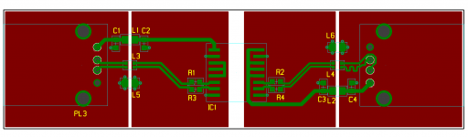
A picture, haven't done my own USB hub (done plenty of other peoples USB hubs though), but considering doing a complete USB hub design with LDO regulated 5V based on the SMSC USB2412 USB hub controller as used in some Audiophile USB hubs, they all have fancy names though so must be better than a hub LOL
This is just a basic design done for something, could use beefier caps and inductor for the 5Vs but as most of the noise is likely to be HF not strictly needed and wasn't for this application. One caveat is you have to be careful of to many CM chokes in the USB data lines can cause signal integrity problems, this is not such an issue when using a ADum device as you have a max speed of 12MHz so you can tailor the rise time to limit the high frequency spectrum and keep the knee frequency down adding further benefits of reduced ringing and overshoot due to minimising the harmonics in the digital USB square wave...
Vladimir a quick question what determines the analogue make up of a digital signal.....
Attachments
Last edited:
Marce, referring to your post 95. I don't think a switch in the ground is a silly option. I think it is a simple tool for the masses. Sure it's not the most elegant option but it's cheap, quick, effective and portable.
Your Hub looks like a great idea. Count me in.
Your Hub looks like a great idea. Count me in.
Last edited:
I have never regarded SET or cheap Chinese tube 'buffers' as normal and sensible, but I realise that not everyone on here is interested in hi-fi. The problem with BGT and its like is that it makes completely nonsense physics claims, either out of sheer ignorance or in an attempt to extract money from the gullible.vladimirb0b said:You might be correct about that worst case mechanism. But if that is what it does and nothing more, is that so bad? People spend small fortunes on amplifiers with a huge amount of even harmonic distortion to create "warmth" and that is accepted as normal and sensible.
Any conductor has stray capacitance to everything else in the universe, unless shielded by a closed conductor around it. Some of this 'everything else' will have an AC potential, and so can induce currents. Adding conductors where they are not needed welcomes these currents; far from improving grounding it degrades it.And can you help me out with what you mean by "stray capacitance"? Are you just referring to the BGT or the ground enhancers, or both?
Yes, add some noise and sometimes things sound 'better'. This is not a good reason to add noise.I have tried foobar plugins that add (relatively) HF noise and they seem to have a favorable effect, or at least an effect. Didn't really decide which sounded better.
Maybe "gibberish" is a little harsh, as that may imply random sounds rather than gross misuse of technical English words. How about 'complete and utter nonsense'; is that more acceptable? If you knew anything at all about electricity you would realise what nonsense it is.I am trying to move on with the thread here in a friendly way but I have to ask, why exactly is BGT smoothing the ground "gibberish"?
That is true as a piece of logic. However, in many cases what is being claimed cannot be happening (as a matter of fact). Thus the burden of proof lies with those making the claim: to show that something is happening, and to come up with a plausible explanation (which does not invoke new physics!). In almost all cases there is no evidence that anything is happening, and attempts at 'explanations' merely exhibit the hopeless ignorance of those making the attempt.vladimirb0b said:Just because (according to you) I don't understand exactly why and how it is happening doesn't mean it isn't happening.
Curious that they got the pinout such that you need to incorporate trace length equalisation ?.....This is just a basic design done for something....
Dan.
LOL I will try🙂
I may have mentioned return currents once or twice... There is no ground apart from the muck we walk on, there are signal return paths and an arbitrary point we call zero volts for a circuit reference (often the same, but for digital signals (the digital ones) the best return paths can be stripline routing between the signals pos voltage and 0V plane, seems it gives the best signal integrity with the return path using one or the other dependant on the current flow. I believe it came from a Howard Johnson note, trying to dig it out.....
Oh and if anyone want any Gerber's of owt' I put up I can probably dig the design out and create them.
Curious that they got the pinout such that you need to incorporate trace length equalisation ?.
Dan.
Its a to b a crossover signal from one connector to the next for USB, a pain but its better to have differential signals length matched otherwise again signal integrity and system noise will increase....
Its also a simple two layer design so easy for people at home to play with, I do believe the PCB is less than 1.5mm to get the correct characteristic impedance for the USB lines.
Last edited:
Maybe "gibberish" is a little harsh, as that may imply random sounds rather than gross misuse of technical English words. How about 'complete and utter nonsense'; is that more acceptable? If you knew anything at all about electricity you would realise what nonsense it is.
I am not convinced that the BGT is nonsense. Think about a battery cell. The potential across the battery is a certain value, say 9V. Current can flow in or out of a battery, through the anode or cathode, and the potential of the cell remains the same, declining slowly if the current is flowing more out than in, (which it doesn't) but pretty much stable. Thus stabilizing the ground voltage.
Add a capacitor or 3 across the terminals to reduce ripple/noise even more, and you have the BGT.
Second time this question has been asked how do you determine the THD of a digital signal.......
Not sure what you mean. The digital signal goes to my E-mu 0404 DAC/Pre, to analog out, to analog in (loopback) then to the ADC, then USB back to computer
Vladimir a quick question what determines the analogue make up of a digital signal.....
Not sure what you mean by this question.
I am not convinced that the BGT is nonsense. Think about a battery cell. The potential across the battery is a certain value, say 9V. Current can flow in or out of a battery, through the anode or cathode, and the potential of the cell remains the same, declining slowly if the current is flowing more out than in, (which it doesn't) but pretty much stable. Thus stabilizing the ground voltage.
Add a capacitor or 3 across the terminals to reduce ripple/noise even more, and you have the BGT.
How does a bit of wire outside of the current loops do anything, the electrons in there would take weeks to get out so it doesn't do anything... its not part of the loop, so as said all it could do is possibly acts an antenna adding rf noise.
There is no ground plane we have decieded that is a misnomer, and if you think a 0V plane or traces are stable ha..... its a living beast.
Current only flows in loops.....
Not sure what you mean. The digital signal goes to my E-mu 0404 DAC/Pre, to analog out, to analog in (loopback) then to the ADC, then USB back to computer
Not sure what you mean by this question.
You say a digital wave form is analogue, I have said it is made up of many analogue harmonics from the base frequency upwards, what determines the upper level of these analogue harmonics......
What if the electron is either used to reduce an ion if current flows into the negative terminal, or oxidize one as current flows out of the negative terminal?
The electrons are slow but there are a ton of them, as evidenced by how slow they can go and still do so much work. Is it I=qt? I can't remember...
- Status
- Not open for further replies.
- Home
- Member Areas
- The Lounge
- Making a usb cable _ data only