Also I assume you have tested with a shorted sound card input to see if there’s no noise coming through the card from the computer due to degrading caps etc.
5% THD on the AC line is not unexpected. The tops of the sine wave are being flattened by rectifiers.
Equipment should be able to deal with distorted AC. I think that you are chasing an equipment problem (ripple coupling into the audio signal).
Ed
Equipment should be able to deal with distorted AC. I think that you are chasing an equipment problem (ripple coupling into the audio signal).
Ed

jean-paul: yes, I will not try to measure line power directly for safety reasons. This is why I used a 2.5Vct transformer, as it produces an output close to what my sound-card can handle.
Yes, I have tested my sound card with shorted input, as well as loop-back.
I saw 5% line distortion back in the 90s when working with Industrial Control Systems. It certainly hasn't gotten any better.
Yes, I have tested my sound card with shorted input, as well as loop-back.
I saw 5% line distortion back in the 90s when working with Industrial Control Systems. It certainly hasn't gotten any better.
Conducted:
Some power mains interference is differential.
Some power mains interference is common mode.
Some problems are conducted from one device on the power mains and another device on that same power mains (conducted emissions).
Radiated:
Some devices radiate electro magnetic fields.
Some devices are disturbed by electro magnetic radiated fields.
EMI regulations specify maximum conducted emissions; and specify maximum radiated emissions.
EMI regulations specify maximum susceptibility to conducted emissions; and specify maximum susceptibility to radiated emissions.
Just because those have maximum allowable amplitudes, and maximum susceptibility, does not mean that 2 devices are compatible.
EMI regulations is one thing.
EMC (Electro Magnetic Compatibility) is another thing.
Often "Good" devices that meet EMI regulations, does not mean they meet EMC (not compatible).
Ground loops; Power Mains loops, etc. are real hard to fix.
Last edited:
Simple test:
Forget the amp, just plug the primary of a suitable vacuum tube OPT into the wall outlet, put a suitable load on it, IE an 8 ohm resistor on the 8 ohm taps, connect up your favorite audio test equipment and measure the THD, plot an FFT, or whatever.
The OPT needs to have a high enough primary impedance so that it will not pass too much power, and the load resistor needs to be sized for that power level as does the OPT itself.
A 600 ohm OPT will put 24 watts into a matched load on 120 volts.
A 1200 ohm OPT will put 12 watts into a matched load on 120 volts.
A 2500 ohm OPT will put 5.76 watts into a matched load on 120 volts.
A 3200 ohm OPT will put 4.5 watts into a matched load on 120 volts.
A 4300 ohm OPT will put 3.35 watts into a matched load on 120 volts.
A 5000 ohm OPT will put 2.88 watts into a matched load on 120 volts.
A 6600 ohm OPT will put 2.18 watts into a matched load on 120 volts.
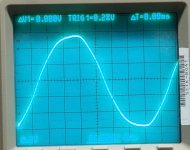
The line power in Florida varied from about 3% to over 10% in THD depending on the time of day and the outside temp. Worst case was about 6 PM on a hot summer day. Visible transformer saturation could be seen on the scope trace. The picture shows a 5% THD day.
Forget the amp, just plug the primary of a suitable vacuum tube OPT into the wall outlet, put a suitable load on it, IE an 8 ohm resistor on the 8 ohm taps, connect up your favorite audio test equipment and measure the THD, plot an FFT, or whatever.
The OPT needs to have a high enough primary impedance so that it will not pass too much power, and the load resistor needs to be sized for that power level as does the OPT itself.
A 600 ohm OPT will put 24 watts into a matched load on 120 volts.
A 1200 ohm OPT will put 12 watts into a matched load on 120 volts.
A 2500 ohm OPT will put 5.76 watts into a matched load on 120 volts.
A 3200 ohm OPT will put 4.5 watts into a matched load on 120 volts.
A 4300 ohm OPT will put 3.35 watts into a matched load on 120 volts.
A 5000 ohm OPT will put 2.88 watts into a matched load on 120 volts.
A 6600 ohm OPT will put 2.18 watts into a matched load on 120 volts.
The line power in Florida varied from about 3% to over 10% in THD depending on the time of day and the outside temp. Worst case was about 6 PM on a hot summer day. Visible transformer saturation could be seen on the scope trace. The picture shows a 5% THD day.
Attachments
Tubelab_com,
Good Idea, Thanks!
I believe the Power Mains Power pole transformer on your street outside: if it has saturation . . .
that will add to the vacuum tube output transformer saturation.
The total saturation is the sum of the two.
With a two channel scope, two transformers, and two power resistor loads . . . do a live comparison.
Just my opinions.
In the case of the picture in post #25 the 6600 ohm P-P OPT is rated for "80 VA @ 42 Hz" (guitar amp use). It was putting out 2.26 watts @ 60 Hz and showed a THD of 5.something % (the picture is grossly out of focus, but looks like 5.2 or 5.5%). All of the saturation seen in the picture is the pole transformer in the backyard or others upstream from it. This was after FP&L had replaced the old steel cased pole transformer with one of the new plastic cased junkformers. We had better quality power before the swap which occurred because of a lightning strike.
I spent some time chasing down the random odd frequency lines on the FFT spectrum a year or so ago. Some are from the line power, but most of them are from the PC and it's monitor as many lines moved when I swapped LCD monitors around. Several more lines come from the LED lighting, with the Walmart LED shop lights hanging over the workbench responsible for a 0.2% increase in THD on a quiet amp. (0.1% THD). The Comcast box (wired internet, router, landline phone, and WiFi internet) on top of the bench (the highest point in the basement) is also a significant contributor, as is the cordless phone plugged into the Comcast box.
I spent some time chasing down the random odd frequency lines on the FFT spectrum a year or so ago. Some are from the line power, but most of them are from the PC and it's monitor as many lines moved when I swapped LCD monitors around. Several more lines come from the LED lighting, with the Walmart LED shop lights hanging over the workbench responsible for a 0.2% increase in THD on a quiet amp. (0.1% THD). The Comcast box (wired internet, router, landline phone, and WiFi internet) on top of the bench (the highest point in the basement) is also a significant contributor, as is the cordless phone plugged into the Comcast box.
One of the issues I hgave been having is that almost all of my FFT scans are plagued with high levels of noise. I had a Viktors 1KHz low distortion oscillator in an aluminium box with a Notch filter, and saw high noise with it. So I built a new 35V power supply using UF4007 diodes instead of 1N4007s, and used a 2.2uF first cap followed by a 220Ohm resistor and then a 1000uF cap. This was followed by a LM317T regulator with 1000uF on the output. This looks reasonably quiet, but the oscillator output still has what I think is too much noise.
Attachments

astouffer, yes and protection diodes per the datasheet.
According to the scope and DMM, no measurable offset.
According to the scope and DMM, no measurable offset.
I believe that any "DC offset" from a power mains transformer, is simply a function of the integral of V-squared of the positive alternation versus the integral of V-squared of the negative alternation.
And that is most often caused by non-symmetrical loads on the power mains transformer at your power pole; or by non symmetrical loads on up-stream power transformers that feed your mains power transformer at your power pole.
You need a scope or digitizer that can do a V-squared operation on both the positive alternation, and the negative alternation.
Comparing the proper V-squared + and - integrals; might possibly give a different result, than a low pass filtered (Average dc) meter.
Your Mileage May Vary
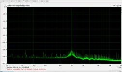
I made an Akitika oscillator a few weeks ago and whilst I didn't see 2ppm distortion, I figured the 5ppm I did see was probably the residual of my dScopeIII test set. Looks like your test set is not locking well to an outside source. Have a look at the triggering. You may be triggering from the internal generator rather than the input signal.But every external oscillator I measure shows high distortion as the Viktors in the previous post, and the AkitikA, second attachment in this post.
As for mains RF interference. It's terrible, but I found low CPS (capacitance between primary and secondary) mains transformers block it. Flat tops and 3% distortion is entirely usual.
That is why R-core transformers are superior.
Yes flat tops and non ideal sinus are normal. That is no issue compared to the RF.
An “ideal” mains source like a generator or a rotary UPS is only that without a load 🙂 Days of resistive loads and no SMPS around are long over so we just deal with this.
Yes flat tops and non ideal sinus are normal. That is no issue compared to the RF.
An “ideal” mains source like a generator or a rotary UPS is only that without a load 🙂 Days of resistive loads and no SMPS around are long over so we just deal with this.
Last edited:
Ok, of the two issues:
1. High line noise.
2. High 2nd harmonic measurements for Suspected good Low Distortion Oscillators.
I am suspecting that problem 1 in addition to lots of SMPS noise on the mains, is a nasty case of ground loops.
Today I un-installed the Asus Strix RAID DLX driver, and removed the card from the computer. I then located and installed a driver for the E-MU 0404 (finally found it stashed in with some old DVDs and CDs) and hooked it up. I then connected the Viktors Low Disstortion 1KHz oscillator to the Mic/Hi-Z/Line input and after some twittling of settings was able to get what I think is a reasonable scan with 0.9Vrms in to the E-MU0404 mic/line input.
As expected, the line noise is mostly gone.
The interesting thing is problem 2. I now show low THD in the expected range with the Viktors LNO.
Why would the internal sound cards (two models and three different cards) show low internal loopback distortion, but higher distortion when driven from an external source while a USB system does not? And how do I fix it?
Attachments

TheGimp,
I have not followed all the posts in this thread, but . . .
Digital links like USB normally do Not have significant effects from ground loops, 1s are still 1s, and 0s are still 0s.
Significant ground loops with USB will cause All the data to be corrupt, and the system will fail.
Go or No-Go.
Analog signal connections (analog links), are always nearly so, or are always nearly not.
A low amplitude ground loop does not totally destroy the signal, just rides on the signal.
Spectrum analyzers and FFTs can show extremely low amplitude un-desired signals.
If you look under the rug, you will see dirt.
Does that sound like what you are observing in Post # 38?
I remember my first look at a spectrum analyzer screen, that was in 1971.
I have been looking at dirt ever since; it often was my primary job in manufacturing, engineering, marketing, and in technical support, now at home and at friends labs.
In the time domain, often the signal looks really clean, but in the spectral domain, we often see what keeps us awake at night.
My latest system:
A ProAc Signature Tablette 2000, with a modified crossover,
A balanced tube amplifier I designed that uses a choke input filter for B+. The power factor is 0.9, and is a very clean load on the power mains.
The only switching supply is in the CD player that has balanced XLR outputs.
When listening seriously, the other devices in the room are purposly switched off (too many switching power supplies on the mains power).
Last edited:
I have tow issues, which I will summarize so people don't have to go back over the past posts.
1. High noise in measurements.
2. High distortion when using an external oscillator, where in soundcard loopback I do not see same high level of distortion (2nd and 3rd harmonics and higher).
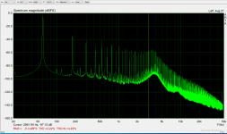
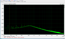
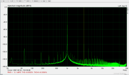
For 1. Here is a scan using the Strix RAID DLX in loopback showing 60Hz and harmonics somewhat below-120dBfs (Baseliine_Loopback.png). Not exactly clean but not terrible.
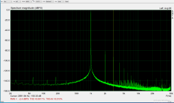
The second scan is an external Low Distortion Oscillator (Akitika) as the source.
Notice the high amount of 60Hz and moderate level of high harmonics. This source is run off batteries, so no conducted noise(?).
1. High noise in measurements.
2. High distortion when using an external oscillator, where in soundcard loopback I do not see same high level of distortion (2nd and 3rd harmonics and higher).
For 1. Here is a scan using the Strix RAID DLX in loopback showing 60Hz and harmonics somewhat below-120dBfs (Baseliine_Loopback.png). Not exactly clean but not terrible.
The second scan is an external Low Distortion Oscillator (Akitika) as the source.
Notice the high amount of 60Hz and moderate level of high harmonics. This source is run off batteries, so no conducted noise(?).
Attachments

Last edited:
- Home
- Amplifiers
- Tubes / Valves
- Mains power garbage in my amp