I have been plagued by what I felt was power line noise in my FFTs of amp circuits for some time.
Some have stated it was IMD, which to some degree it looked like, however I was convinced I had power issues greater than IMD.
To that end I am going to investigate power line noise from my mains, and power supply noise from simple SS rectified circuits which I was using to power a low noise (Victors) 1KHz oscillator which exhibited high background noise.
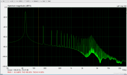
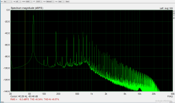
First up is a simple scan of powerline noise made using an FFT (ARTA) program, of the output of a 2.5VAC CT transformer (Triad F-6X) through a resistor divider (470R-470R) to prevent overloading the sound card front end.
Not a pretty sight, is it? This has been filtered (to some degree) by an isolation transformer which is used to separate my test circuits from the rest of the house system.
Next I will try using a line filter to clean up the mess.
Some have stated it was IMD, which to some degree it looked like, however I was convinced I had power issues greater than IMD.
To that end I am going to investigate power line noise from my mains, and power supply noise from simple SS rectified circuits which I was using to power a low noise (Victors) 1KHz oscillator which exhibited high background noise.
First up is a simple scan of powerline noise made using an FFT (ARTA) program, of the output of a 2.5VAC CT transformer (Triad F-6X) through a resistor divider (470R-470R) to prevent overloading the sound card front end.
Not a pretty sight, is it? This has been filtered (to some degree) by an isolation transformer which is used to separate my test circuits from the rest of the house system.
Next I will try using a line filter to clean up the mess.
Attachments

I believe all the garbage is due to switching power supplies which are ubiquitous to the electronics we use every day. Wall Warts for charging our cellphones, fitbits, etc. CFLs, LED lights, intelligent (? Yea right) Toasters, ovens, TVs, refrigerators, Google Home, Nest thermostats, etc.
Our power line is contaminated with switching power supply noise.
The solid state rectifiers followed by large capacitor values for fast rectification and small conduction angles are for the most part responsible. The switching power supplies help fill in the rest.
Our power line is contaminated with switching power supply noise.
The solid state rectifiers followed by large capacitor values for fast rectification and small conduction angles are for the most part responsible. The switching power supplies help fill in the rest.
Last edited:
Can't say if power has always been bad in one way or the other, but I don't see it ever getting better. Makes me wish that I could run everything strictly on batteries despite new issues. Yup, specially made audio system designed for use with just batteries and nothing else. I am a dreamer, that's for sure.
Is that through an IEC inlet filter or direct?
I have an ADC project and basically the more filtering the better!
Below 1MHz you could use a voltage reg (maida etc) for an easy -60dB but above you’re looking at passives (CMC, ferrites etc). If you've got big iron RCLC on the power supply that should nail a load.
Also what shielding do you have in the amp and how is it laid out? What grounding are you using?
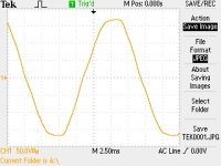
What does the scope show further up? (An alternative is go noise hunting with a tinysa).
I still get an annoying 50Hz mains spike which I suspect is through one of the bench supplies via the clock prototype. This project has made me a bit of a filter/noise junkie. Below - I used LT3080s on the input, with shunts, and with ferrites in pi filters (600R@25MHz and 20R@25MHz) but ground loop removal make a large difference (-27dB)
Lastly - can the amp designs provide some PSRR? (ie akin to Broskie's process of deliberately feeding noise into the signal path to cancel out).
You could add a galvanised mesh into the plaster/ceiling of the room to reduce external noise that's being radiated, but another option is look at mumetal, copper and steel in progressive shielding.
A final option... is use an active choke - have sensing choke attached to the inverting input of an opamp that drives a driving choke. That way you don't have sand in your signal path.. but it does attempt to cancel noise.
If you are using a victors then you probably know all of this but doesn't help to be pedantic in tracing 🙂
I have an ADC project and basically the more filtering the better!
Below 1MHz you could use a voltage reg (maida etc) for an easy -60dB but above you’re looking at passives (CMC, ferrites etc). If you've got big iron RCLC on the power supply that should nail a load.
Also what shielding do you have in the amp and how is it laid out? What grounding are you using?
What does the scope show further up? (An alternative is go noise hunting with a tinysa).
I still get an annoying 50Hz mains spike which I suspect is through one of the bench supplies via the clock prototype. This project has made me a bit of a filter/noise junkie. Below - I used LT3080s on the input, with shunts, and with ferrites in pi filters (600R@25MHz and 20R@25MHz) but ground loop removal make a large difference (-27dB)
Lastly - can the amp designs provide some PSRR? (ie akin to Broskie's process of deliberately feeding noise into the signal path to cancel out).
You could add a galvanised mesh into the plaster/ceiling of the room to reduce external noise that's being radiated, but another option is look at mumetal, copper and steel in progressive shielding.
A final option... is use an active choke - have sensing choke attached to the inverting input of an opamp that drives a driving choke. That way you don't have sand in your signal path.. but it does attempt to cancel noise.
If you are using a victors then you probably know all of this but doesn't help to be pedantic in tracing 🙂
Attachments

Last edited:
Also don't underestimate what is coming in through the air. Almost all by own choice 🙂
If the cause can not be taken away then the remedy is in coils/filters. Simplest but in reality often hardest for many is to abandon SMPS and disable wireless/bluetooth stuff. For some reason these items are vigorously defended by many but it is more an issue like cutting ones own finger and then trying to find a band aid. If highest possible audio quality is the goal then clean power is an absolute first requirement.
Batteries will not cure this 100%.
Last edited:
Looks about right to me. One should not expect anything cleaner from the power grid these days.
For what it's worth, my amps and preamps all have linear power supplies/rectifiers. Most of which are tube-based rectifiers, but some of the smaller power requirements do use silicon. Not a single one has any problem with power line noise, ground loops, hum, or buzz. I can provide FFT's if it matters.
Oh, and also a combination of AC and DC heating for the tubes depending on the stage.
Other than my strong preference for using electrostatic shielded transformers (which isn't always easy to get) I have absolutely no power line filtering. Magnetic coupling with standard steel is sufficient filtering.
A good power supply could care less about the spectrums you have shown, and it doesn't need to be exotic, just designed with standard engineering principles.
Attachments
Apparently most of the crap you see is 60Hz harmonics. You would need to zoom on the highest part of the spectrum, but anyway, a 60Hz Xformer is not good at transmitting high frequencies, except if it is a toroidal.First up is a simple scan of powerline noise made using an FFT (ARTA) program, of the output of a 2.5VAC CT transformer (Triad F-6X) through a resistor divider (470R-470R) to prevent overloading the sound card front end.
Not a pretty sight, is it? This has been filtered (to some degree) by an isolation transformer which is used to separate my test circuits from the rest of the house system.
Non-PFC supplies can create an harmonic spectrum like yours (including linear ones, to a lesser degree)
Your small transformer could significantly contribute to the mains harmonics, because such transformers operate partly in saturation. A way round would be to put the top resistor of the divider in series with the primary (properly scaled, obviously), and load the secondary with the foot resistor.
If you want to see the upper part of the spectrum correctly, you can use a CMC choke as an isolation transformer: a 2x22mH for example.
This has to be done with great care:
-Using a CMC in this role is not legit, because it only has a X isolation level, not the Y that is required in theory. This means that you have to chose one where the two windings are clearly visible, and well separated/insulated.
-You need to place a X-rated capacitor in series with the primary: 100nF for example, and it has to be damped with a resistor, 100 ohm 1~2W for example. The secondary also has to be damped, also with a 100 ohm resistor; 0.25W is sufficient.
-It is essential to protect the sound-card input, because transients, especially when you connect it, would kill it instantly. Use a bidirectional transil having a voltage compatible with the sound card.
-Be extra-careful, because mains is involved, and use an earthed secondary setup: in case something goes, your GFI will protect you
Elvee, thanks. I have several CMCs which fit the bill. I will try this, although I believe my sound card only goes to 48KHz so I probably won't see much. The sound card (Asus Strix DLE) can sample at 192KHz, but the FR specification of the card is stated at 10Hz to 48KHz, so I presume thay set the max brickwall filter to 96Ks/s.
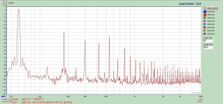
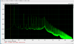
Lets start with aCorcom 1EBH1 IEC inlet filter. I got these at a HamFest three for a dollar. There is a bit of improvement above 10KHz.
The name of the file contains the filter model. CC is Corcom.
Lets start with aCorcom 1EBH1 IEC inlet filter. I got these at a HamFest three for a dollar. There is a bit of improvement above 10KHz.
The name of the file contains the filter model. CC is Corcom.
Attachments
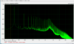
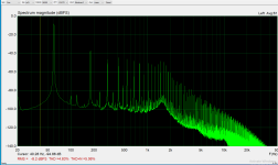
Some more filters, smallest to largest per the picture of filters.
None of the filters have much effect below 10KHz where most music content is.
Also, the physically larger the filter is, the better it performs. There is no free lunch.
The big Corcom is around $100 IIRC. It has a significant impact above 20KHz.
None of the filters have much effect below 10KHz where most music content is.
Also, the physically larger the filter is, the better it performs. There is no free lunch.
The big Corcom is around $100 IIRC. It has a significant impact above 20KHz.
Attachments

IIRC, power supplies below 100W do not require PFC and therefore have narrower conduction angles and produce more noise back on the power lines.
If I unplug every device not in use (computers, TV, radio, etc) and turn off all the lights (they are all LED now), I see a 5 to 10dB reduction from 4KHz up. Otherwise it looks the same.
If I unplug every device not in use (computers, TV, radio, etc) and turn off all the lights (they are all LED now), I see a 5 to 10dB reduction from 4KHz up. Otherwise it looks the same.
Maybe that is not the whole story. High frequency signals intermodulate.None of the filters have much effect below 10KHz where most music content is.
It is worst with toroids. These need mains filtering.
Last edited:
Valid point Jean-Paul.
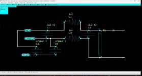
I may try building a line filter since I have a ready supply of CMC and a selection of X2 caps. I am a little short on Y caps (1, 4.7, and 22nF).
I may try building a line filter since I have a ready supply of CMC and a selection of X2 caps. I am a little short on Y caps (1, 4.7, and 22nF).
IME one is best off with a mains filter with separate filtered outputs. I built one but wanted it smaller and use a single filter now. Still better than no filtering at all.
The older Belkin PureAV filters are both effective and good looking. Separate outputs, PE detection, overvoltage protection, overcurrent protection, a delayed output for amplifiers etc. I lent one out and only got very positive comments.
The older Belkin PureAV filters are both effective and good looking. Separate outputs, PE detection, overvoltage protection, overcurrent protection, a delayed output for amplifiers etc. I lent one out and only got very positive comments.
Last edited:
Remember that CMC's do just that: common-mode. The effect of a "good" CMC (ie. one that has minimal parasitics) on your spectrograms should be minimal, since your measurement is in differential mode.Valid point Jean-Paul.
I may try building a line filter since I have a ready supply of CMC and a selection of X2 caps. I am a little short on Y caps (1, 4.7, and 22nF).
In practice, CM and DM can leak into one another, but if you are serious about cleansing the DM, you should also add single inductors, or non-cancelling coupled inductors. Ideally, they should be used together with RC damping networks, as strong resonance frequencies will appear (in CMC's too, although the phenomenon is more subtle and is generally addressed with gas surge-arrestors bypassing the inductors, or connected to the PE when possible)
It is unlikely that a DIY filter will be performing as well as well chosen, certified and tested shielded industrial filters that may even have an IEC inlet, internal fuses and a power on/off switch. Don't bother picking one that filters in the audioband but choose one that filters HF/RF (as they are designed for). You can filter stuff in the audioband at the secondary/DC side.
One should be careful with mains connected stuff. Please be cautious & careful and remember that your test equipment may be the short circuit when measuring mains stuff. In fact I would emphasize not to measure at the mains side of matters unless one is experienced.
One should be careful with mains connected stuff. Please be cautious & careful and remember that your test equipment may be the short circuit when measuring mains stuff. In fact I would emphasize not to measure at the mains side of matters unless one is experienced.
Last edited:
Unplugging my wifi router gets me from 60 visible networks to 59. I guess I could go and bang on my neighbours' doors. And note: I live in a house. Not an apartment. This is inner city living... 🙂Simplest but in reality often hardest for many is to abandon SMPS and disable wireless/bluetooth stuff.
Tom
Yes distance is a key factor. The own RF sources signals are the hardest to get rid of in audio circuits. If you walk around with your router connected to extension cables you can easily notice this. In the past I did RF site surveys for DECT networks, buildings with high power GSM transmitters on the roof are the worst for inhabitants with an audio hobby 🙂
One can not change the world but one can change ones own situation or optimize it. Metal casings, PE, shielding, filtering, linear PSUs are a few ways to reduce the garbage. The opposite way is to give in and accept ones own introduced pollution. Way easier but IMHO contradictory with building HQ audio and highest possible performance.
One can not change the world but one can change ones own situation or optimize it. Metal casings, PE, shielding, filtering, linear PSUs are a few ways to reduce the garbage. The opposite way is to give in and accept ones own introduced pollution. Way easier but IMHO contradictory with building HQ audio and highest possible performance.
Last edited:
- Home
- Amplifiers
- Tubes / Valves
- Mains power garbage in my amp