It is kind of obscure. First page in the upper right there is a mechanical drawing. Just below mid way down on the right side of the drawing is a pin-out diagram depicting the internal structure of the FET including the intrinsic revers protection diode from Source to Drain, and two back to back zeners from Gate to Source.
It is kind of obscure.
Thanks, I see it now. Another great use for 200% zoom.
Just curious, generally they seem to be depicted and installed back to back where in that drawing they are nose to nose. Does the order matter, so long as they are opposed?
As others said the back-to-back diodes are to protect from G-S breakdown. I built a simple source-follower regulator once without these and it worked great until I powered it down(there was some capacitance in the load), after which it functioned as a short circuit.
It doesn't matter if they are back-to-back or nose-to-nose. With all of the larger parts installed it will be a bit of a pain to solder them I would think. I would just use the ones inside the fet.
EDIT: What are you using for D6 and D8? I usually leave these out for positive regulators.
It doesn't matter if they are back-to-back or nose-to-nose. With all of the larger parts installed it will be a bit of a pain to solder them I would think. I would just use the ones inside the fet.
EDIT: What are you using for D6 and D8? I usually leave these out for positive regulators.
Last edited:
As others said the back-to-back diodes are to protect from G-S breakdown. I built a simple source-follower regulator once without these and it worked great until I powered it down(there was some capacitance in the load), after which it functioned as a short circuit.
It doesn't matter if they are back-to-back or nose-to-nose. With all of the larger parts installed it will be a bit of a pain to solder them I would think. I would just use the ones inside the fet.
EDIT: What are you using for D6 and D8? I usually leave these out for positive regulators.
On this one I will leave D2 and D4 out. I'm also going to shunt R1 and see if I can get away with that. I did a point to point thing with D9 so as to avoid all the SMDs this time.
I saw your notes about D6 and D8 but it didn't sink in until after I had them soldered in. I understand they cause no harm so they stay in.
Thanks
Last edited:
They shouldn't hurt as long as the zener voltage isn't lower than the voltage drop across the regulator. If so, they will release their smoke.
Sorry about the SMDs. I wanted five of these to fit in a small space in the amp I designed them for and that was the only way to make them this small.
Sorry about the SMDs. I wanted five of these to fit in a small space in the amp I designed them for and that was the only way to make them this small.
They shouldn't hurt as long as the zener voltage isn't lower than the voltage drop across the regulator. If so, they will release their smoke.
Sorry about the SMDs. I wanted five of these to fit in a small space in the amp I designed them for and that was the only way to make them this small.
I don't think that will happen, but without the smoke, they can no longer cause trouble. I could clip them out I suppose.
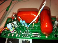
I get it about the SMDs. If it won't hurt you feelings seeing your nice board all hillbillyed up, I'll post the photos of the point to point workaround. 😱
Attachments
I tested this with a transformer on a variac set for 400VDC after rectification and just a 22uf cap. Ripple in is better than 1.5 volt.
Ripple out of the Maida set at 175 volts and and 9ma current (a 20K load) is 1.7 ma measured with a Fluke 87. I have a Tek 453 and it sees about 100 mv of some very high frequency ripple. 2/3 waves per scale at 1 us. What's that, 667 khz?
Edit: And it's really about a volt, I'm using a 10:1 probe.
I max out at about 180 volts with the 150R and 20K pot so I'll need a bigger pot for my adjustable HT source.
I'm out of time for today but I'll try this again with my Lambda DC power supply and see if the high freq stuff goes away.
Last edited:
The hash is still there with the Lambda, but the shape, amplitude and freq are all a little different is different. Frequency went up to about 1 gHz and the amplitude went down to 400 mv (40 with the 10:1 probe). It looks like the top of the wave form has been clipped.
And by the way, you don't want the D4 and D6 zeners with a positive supply. They make a little "fizzzts" sound, but just once. Not really so much smoke as you'd think. No harm to the rest of the circuit.
And by the way, you don't want the D4 and D6 zeners with a positive supply. They make a little "fizzzts" sound, but just once. Not really so much smoke as you'd think. No harm to the rest of the circuit.
I have no gate stopper. I shunted those pads with wire. I assume that's the cause of the high freq waveform. Anyone have other ideas?
The first Maida regulator I built was point-to-point. I noticed that I got small spikes at a rate of 120Hz. I theorized it was garbage from the diode switching from the bridge getting through the regulator. I started using diodes with a softer recovery, RC snubbing the the transformer secondary, and building these on circuit boards with tighter layout. The spikes disappeared. Unfortunately, I did all three at once so I don't know which makes the bigger difference.
I was unable to see anything but a flat line on the output of the regulator I built with my Tek 465. I had difficulty measuring ripple with my DMM because it doesn't measure properly on an AC setting with DC offset. It's like a $35 Extech meter so not the nicest meter out there. I capacitively coupled to the regulator output and was measuring about the same ripple as when I short the probes, so I give up on using that meter for this purpose.
Anyway, keeping in mind that this thing isn't perfect at attenuating high-frequency garbage coming in, it should work pretty well. The solution for me has been to eliminate the crap coming in, then it won't come out.
I think the stopper could be your main issue. Nothing I hate more than when I only need a 4 cent resistor to finish something.
Let us know how it goes.
It's like a $35 Extech meter so not the nicest meter out there. I capacitively coupled to the regulator output and was measuring about the same ripple as when I short the probes, so I give up on using that meter for this purpose.
Heath,
There will be no argument from me that Fluke Meters are well worth their cost, but one meter just isn't enough. I picked up an Amprobe AM-240 for about $40 last year as a "second meter" and I am very very satisfied with it's capabilities. It is the greatest bang for the buck in the DMM category I have found. Have a look. I don't think you will be disappointed. GENERIC VENDOR LINK
Hi Guys
Has anyone tried running Maida Regulator down to 48v?
Rectified voltage is 53.2 vdc
Amp is drawing 210ma ( Pete Millets Starving Student)
I,m getting a fair bi of hum, have played about with all of the earth contacts to the earth bar...no luck, wondered if better regulation would help?
Cheers
Has anyone tried running Maida Regulator down to 48v?
Rectified voltage is 53.2 vdc
Amp is drawing 210ma ( Pete Millets Starving Student)
I,m getting a fair bi of hum, have played about with all of the earth contacts to the earth bar...no luck, wondered if better regulation would help?
Cheers
With only 5 V drop-out, the Maida regulator won't be very happy. Mike Maida's original circuit required near 10 V as I recall, though, you get better results if you give it a bit more headroom.
My 21th Century Maida regulates down to 10-ish V drop-out as well.
Aside from that, there's no reason a Maida regulator shouldn't work down to 48 V out.
I'm thinking your hum issue is because of poor regulation as you're starving the regulator of headroom. I suggest either using a different regulator or increase the headroom on the regulator by dropping the output voltage or increasing the input voltage.
But you know.... There's a high-voltage version of the LM317. It's called LM317HV. It can handle up to 60 V from input to output, hence, would work as a stand-alone regulator in your circuit.
~Tom
But you know.... There's a high-voltage version of the LM317. It's called LM317HV. It can handle up to 60 V from input to output, hence, would work as a stand-alone regulator in your circuit.
~Tom
TL783 is also a good 125v regulator. http://www.ti.com/lit/ds/symlink/tl783.pdf
Thanks Tom and Jackinnj
I decided to fully rebuild the power supply including a larger tranny, went for the TL783 as the LM317HV's are $19 each here in NZ!!! I got a bag of 5 TL783's for $23 from RS Components...no brainer really.
The hum has almost completely gone, will play about with earthing arrangements, and might try a star earth rather than Earth Follows Signal?
Thanks again for the advice.
Cheers
Problem with negative Maida regulator
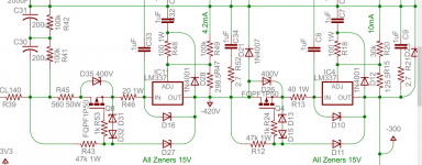
Hi. I am building ±150V Maida regulators based in part on the schematics at post #28 (1st attachment).
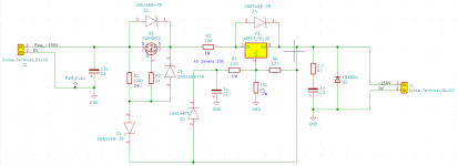
My schematic is the second post.
I was so confident I went straight to PCB design and production.
Being cautious I’m running 2 tests before hitting them with ±175V
The negative one produces -0.8V in the first test and destroys the zener protecting the P-channel MOSFET in the second.
Thinking there might be a problem with my PCB design I built a standard negative regulator on a solderless breadboard (worked perfectly so I have the LM337 pin-out right) and then the Maida circuit.
The latter had the same -0.8V output with the -19V test. I didn’t try -57V because I have a limited supply of 15V zeners.
I’ve triple checked (more!) the pin configuration of the P-channel MOSFET.
Does anybody have any suggestions for something I’m missing please?
Hi. I am building ±150V Maida regulators based in part on the schematics at post #28 (1st attachment).
My schematic is the second post.
I was so confident I went straight to PCB design and production.
Being cautious I’m running 2 tests before hitting them with ±175V
- with ±19V and a short in place of the large value voltage-setting resistor looking for roughly ±1.25V at the output
- With ±57V from an amp power supply I have handy and the voltage-setting resistors set for ±25V out.
The negative one produces -0.8V in the first test and destroys the zener protecting the P-channel MOSFET in the second.
Thinking there might be a problem with my PCB design I built a standard negative regulator on a solderless breadboard (worked perfectly so I have the LM337 pin-out right) and then the Maida circuit.
The latter had the same -0.8V output with the -19V test. I didn’t try -57V because I have a limited supply of 15V zeners.
I’ve triple checked (more!) the pin configuration of the P-channel MOSFET.
Does anybody have any suggestions for something I’m missing please?
Attachments
- Home
- Amplifiers
- Tubes / Valves
- Maida Regulator PCB