GM,
I think I was referring to amplitude ratios while you are referring to power ratios which is square of amplitude as P=V^2/R?
In amplitude signal world dB = 20 log(Vhigh/Vlow)
I think I was referring to amplitude ratios while you are referring to power ratios which is square of amplitude as P=V^2/R?
In amplitude signal world dB = 20 log(Vhigh/Vlow)
Last edited:
BMS,
I wonder if rectilinear cabinets tend to have more of a problem with internal reflections. In my curvy walled DCR, the impulse looks pretty clean and free of reflections. Not a A7.3 but here to demonstrate effect of non rectilinear walls on IR.
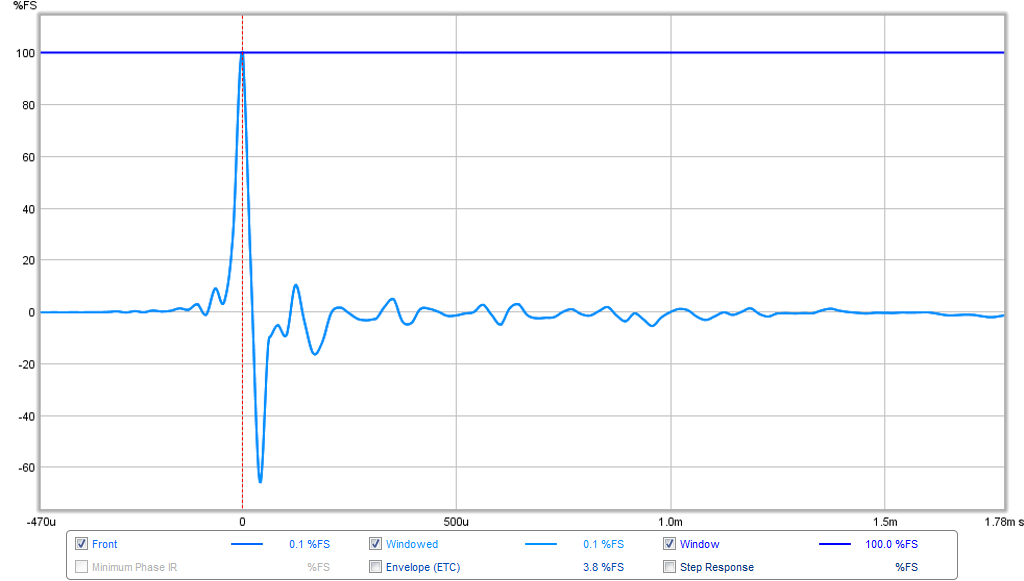
And here is same driver IR in an open baffle.
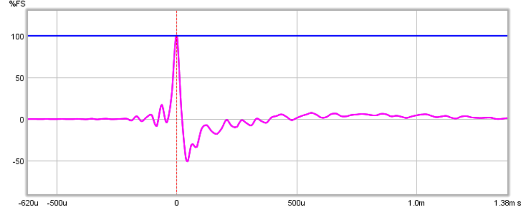
I wonder if rectilinear cabinets tend to have more of a problem with internal reflections. In my curvy walled DCR, the impulse looks pretty clean and free of reflections. Not a A7.3 but here to demonstrate effect of non rectilinear walls on IR.
And here is same driver IR in an open baffle.
In my experience the only way a cabinet tends to mar a drivers distortion performance is if the rear of the cone is extremely covered up by the cabinet. If it's free to breathe then the box wont typically cause any issues.
Normally though, if box resonances or reflections are the culprit they tend to show up only at specific frequencies, rather than being broadband. They also show up in the impedance plot as wiggles or bumps, deviating from what you'd expect from a purely inductive rise. Of course you'd need to compare the driver measured in free air vs in the cabinet to see if any bumps were showing up. Full range drivers typically display a number of these anyway as exploiting resonances is inherent to their design as a way of extending the high frequency response. Getting this effect comes at a price though because lightening the cone causes it to be less pistonic further down in the midrange, so you get issues occurring there too. Now full range drivers aren't the only ones that succumb to these mid band resonances, as other heavier soft cones do too. Heavy, very rigid cones, like the SEAS excel drivers, are completely free from any resonances, except of course for their bell mode resonance high up in frequency.
Nevertheless, if you wanted to pin box resonances/reflections on the problem, you'd need to make sure the bumps you were seeing in the impedance were actually being caused by the box and not the driver.
The dip encountered at 1.2kHz is unlikely to be box related as this is present in Mark's own measurements, but the box could quite easily be designed to reduce its effect. 1.2kHz is smack bang in the frequency range where the primary diffraction peak can show up for cabinets with the range of widths we're talking about using with these drivers. If you designed the width accordingly it would compensate quite nicely for the inherent dip. Also some internal cabinet reflections/resonances could help to reduce its effect too, or make it worse, but this would be incredibly unpredictable and getting the compensatory effect from cabinet diffraction would be a much better choice - this could explain why some peoples measurements present with the dip and some don't.
In any case the simplest way to confirm measurements, one way or another, would be to get a 50x50cm baffle of MDF, flush mount the driver in the centre of it, chamfer the rear of the cut out and do some gated far field measurements in a properly configured room (ie one that's had all reflective surfaces from furniture etc removed). I would also suggest using STEPS to perform distortion measurements, that is rather than swept sine stimuli as it tends to give better end results.
Yes the 50cm baffle wont be large enough to give low end accuracy and no doubt your room wont be either. But it should be good enough to satisfy anyone's doubts as to the measurements usability from around 400Hz and up.
GM,
I think I was referring to amplitude ratios while you are referring to power ratios which is square of amplitude as P=V^2/R?
In amplitude signal world dB = 20 log(Vhigh/Vlow)
What I posted are power ratios, yours are voltage ratios, so must be converted back to power ratios for response plots as I understand such things.
GM
gee, if we were looking for something simple and absolute, we probably need to find another hobby 😉
That's why I have two hobbies. Speakers and drinking. If one isn't working at the moment, the other probably will. See? It's not that hard.
True. I haven't measured my MA A5, and I'm not slighting the brand either, BUT mine exhibit an AUDIBLE resonance at almost exactly 400hz, which isn't obvious on the published specs.
These plots could be inaccurate, hesitant to say that.
OR the resonance isn't easily found through a FR plot alone.
There is alot a measure excludes as well as the info it shows

What was exact measurement conditions? Did you merge near and far field data?
Gating and so on?
Is this only one automated gating and no near field splice?
Measuring Mark Audio Alpair-10 gen-2
Last edited:
True. I haven't measured my MA A5, and I'm not slighting the brand either, BUT mine exhibit an AUDIBLE resonance at almost exactly 400hz, which isn't obvious on the published specs.
I don't have any MA drivers, but I had a problem with peak at around 500 Hz which was produced by the box and did go away with damping.
I don't have any MA drivers, but I had a problem with peak at around 500 Hz which was produced by the box and did go away with damping.
This occurred when measuring Fs using a frame and string a la studio mic style, and was an obvious cone/suspension termination resonance. Obvious at very low power.
I had suggested this type of suspended by string measurement with mic at close range and low power once as a means to measure the inherent mechanical resonances in a driver and people said it was a pointless measurement. Not pointless if you find something though. How many dB is the 500 Hz peak?
All of the third party measurements seem to be consistent having the same wiggles and jiggles in response. Only MA's differ.
I'd like to hear them but have not yet had the pleasure because of all the Fostex and TB in my house.
I'd like to hear them but have not yet had the pleasure because of all the Fostex and TB in my house.
I had suggested this type of suspended by string measurement with mic at close range and low power once as a means to measure the inherent mechanical resonances in a driver and people said it was a pointless measurement. Not pointless if you find something though. How many dB is the 500 Hz peak?
I haven't measured FR so no idea of the peak amplitude, i was running impedance curves. However the same resonance occurred in both drivers i own and id have to dig out the impedance curve to tell you the Z and hence the drive voltage (1k R Cal'd for 10 ohm = 10 mV)
I had suggested this type of suspended by string measurement with mic at close range and low power once as a means to measure the inherent mechanical resonances in a driver and people said it was a pointless measurement. Not pointless if you find something though. How many dB is the 500 Hz peak?
It's only really pointless because flush mounting the driver to the centre of a large piece of MDF is more than enough and doesn't come with all the issues that string mounting would.
You're good man, you're good. 🙂
I thought I could distill it down to an essence with which you could identify
What, should we stop?

The reasons that driver-on-a-string measurements are pointless is 1) if you go back to Olson's defraction drawings, you will see that this method is guaranteed to introduce defraction artifacts based on driver diameter and 2) no one is going to use a driver this was in an actual speaker. I've been tied up with real life and have not had time to play with what-ifs lately, but in the next month or so I intend to do some comparisons on an IEC baffle.
BTW, I hope everyone spent some quality time with Troels' treatise on microphone mounting.
Bob
BTW, I hope everyone spent some quality time with Troels' treatise on microphone mounting.
Bob
What was exact measurement conditions? Did you merge near and far field data?
Gating and so on?
Is this only one automated gating and no near field splice?
Measuring Mark Audio Alpair-10 gen-2
Thanks for your link. I remember that one. Ouch 😉
I answer your questions in the link I posted, but that was at around 1m iirc. Maybe 0.8m. No nearfield splice because I usually opt for GP splice and don't feel the A6 and FF85 (the two drivers I measured at the time) are worth using for LF so I left that out. The gate F is noted on the graph at 150hz which is selected based on the first reflection. I keep the gate just inside that reflection about 0.25ms iirc. The nearest reflection was about 1.7m away iirc. All in that link if you wanted to know.
BTW. I'm ryanbouma over on TT so you might recognize me 😉
- Status
- Not open for further replies.
- Home
- Loudspeakers
- Full Range
- MA driver measurements