Hopefully not.....in the real world R and L are not in the ground path.
I don't know if my drawing can confuse?
I don't know if my drawing can confuse?
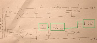
Attached is your drawing from post #53....You have the lower R and L attached to ground. On the lower portion of the supply, you should put R and L on the negative rail. The way you have it now, the voltage output from the supply is asymmetric, which could be the reason why you have an offset. Unless you drew it incorrectly....
Attachments
My DC-offset is perfect now.
I see your change as now you have connected R and L in neg. rail to Gnd. That is not how I have implemented it.
Think we need a "3rd party" to be the judge 🙂
Maybe it is just a "drawing confusion".
I see your change as now you have connected R and L in neg. rail to Gnd. That is not how I have implemented it.
Think we need a "3rd party" to be the judge 🙂
Maybe it is just a "drawing confusion".
no need for 3rd party
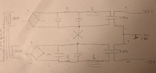
additional series filter elements ( be it R or L) needs to be symmetrically placed - in rails , not GND
so, as MegaAmp drew in post #58
though, if you used Store pcbs, they are most likely like that, and you just made a mistake while drawing
additional series filter elements ( be it R or L) needs to be symmetrically placed - in rails , not GND
so, as MegaAmp drew in post #58
though, if you used Store pcbs, they are most likely like that, and you just made a mistake while drawing
OK.....yes, I understand now.......mis-drawing in my first drawing.......it is implemented symmetrical......
Now schematic corrected. In my mind it was so all the time........
But it seems DC is still hunting me. It is not critical that DC offset jumps around and stays inside 100 mV but it is a strange behavior that a DC rail goes 0.2 - 0.3 V down and not stable. Now with AC stabilized at 230.6 V RMS. A bit of sound from toroid when this happens my only explanation is DC. Also that suddenly it can stop and everything is stable and silent.
I read this article:
SoundStage! Max dB - The High-End Mythology of the Toroidal Power Transformer (07/1998)
EI-core transformers still has some advantages. Hand wound?
Maybe next toroid should be with air gab?
Will see when DC-blocker shows up.
Attachments
I now have a new theory. Maybe not for the tranformer hum but for the unstable DC-offset caused by unstable DC-rail.
I use a NTC as inrush limiter. A 10 ohm type a little more powerful than a CL-60 so it can take a few watts more (that may be the problem) and also when I run a 230 VAC system primary current is less than in a 120 VAC system (and I also run M2X as mono blocks). So 4 times less current than in a 120 VAC M2X stereo amp?
I noticed it was only about 50 degree hot or so.....and at that temperature it has some resistance and my theory is that my DC rail is "modulated" by this device. I tried to use a hair dryer and heat it up and then my rails came back and DC-offset back to about 0.....or very close.
A good theory?
You can put a SPST switch in parallel with the NTC, and use that as a soft start cut-out. Power on, wait 3 seconds, flip the switch on, and you get full rail voltage. Not sure if you've specified what size your transformer is previously, but if its <500VA, dispense with the NTC altogether.
It is 400VA toriods. I will try to start it directly on the mains. Now I also have a re-generator I assume this will limit the in-rush current. I need higher value fuses. I guess 4AT should do it.....the protection will be less of course. It is more like a short circuit protection. But I have rail fuses.
I think that solved the problem. Rails raised from about 22.5 to about 22.85V and are symmetrical. DC offset stable and can be adjusted to 0 and seems to stay there. Toroid's are silent......very silent so I think the "cool" NTC has caused some distortion. We will see during the next days........but I think this time...... 🙂
Everything still stable. DC-offset < 5mV on both amps after warm-up and it never exceeds 40 mV during warm-up so think problem is fixed.
good, now we know that you didn't had a problem in first place, except mains Gremlins 🙂
you can make relay equipped Soft Start, but use 3x10R NTC inn series, instead of fixed resistors, and set long delay - 10s or so
you can make relay equipped Soft Start, but use 3x10R NTC inn series, instead of fixed resistors, and set long delay - 10s or so
Yes, that would be a nice solution to be able to use primary fuses that actual protects. Now I have the mains re-generator to protect. It will go into protection if 350 Watt or so is consumed for some seconds. There are no problems starting both 400 VA toroid's on the re-generator. I use 4AT fuses at primary in the moment.
Regarding use of a NTC as standalone in-rush limiter in a 230 VAC system and in a mono block design with a small amp like M2X is not recommended. It has really been confusing that after I made a change it seems to work and then suddenly the problem came back. So when not enough current are running through these devices their impedance it quite high and not stable and then make rails unstable so they can go up and down. In my case like 0.1 - 0.4 VDC. A 0.1 VDC change seems to correspond to about 50 mV offset which is not a problem and 200 mV not a problem either but I wanted to find out why this happened. The re-generator with a stabilized mains was a help to find the cause of the problem.
In a M2X stereo amp in a 120 VAC system primary current will be about 4 times higher and then NTC will be well below 1 ohm..... I think..... and will not cause large rail variations.
A much smaller size NTC in my case could maybe work. It is about using the correct one for the purpose 🙂 ....you always learn something......
Regarding the NTC I should have looked closer to the data sheet before I used it. There are some nice curves of current vs. impedance and also temp vs. impedance. But I don't now how small you can get them......if I could find one for my purpose but I think I am more attracted by a "relay solution" with some time delay in the future.
I think this may be a "never ending story".
It seems I have not really found the "root cause" of the problem. From time to time I still see that suddenly the DC offset gets unstable caused by especially one rail drops 0.1 - 0.3 V and goes a bit up and down. I still think it was good to remove the NTC as it was not designed correct for the purpose and then I got 0.3V higher rails and lower impedance. I have a new theory what the "root-cause" could be.
I can measure the voltage drop all the way down to just after the diode bridge (I use standalone diodes on Universal PCB). The AC from secondary looks fine. Then I looked up the data of the diodes I use and maybe they are not the right size for the job. It is the repetitive peak feedforward current I am after which drops with temperature. It fits with that it takes a while before I see some instability and also if I switch off a amp and wait 20 sec. and switch on again it starts up stable.
I use these diodes:
https://docs.rs-online.com/d3cc/0900766b8149fd43.pdf
They are one the "thin" side?
What happens if peak feedforward current is exceeded? .....larger unstable voltage drop?
I use 33mF caps on Universal PCB and additional 33mF after the choke. So some Amperes are expected during charge of the caps? more than 20A probably?
Is the new theory a possible root-cause?
I am very close to buy some 35A bridges and plan to break off the diode part of the PCB and maybe use it in a future project which requires less power.
Regarding use of a NTC as standalone in-rush limiter in a 230 VAC system and in a mono block design with a small amp like M2X is not recommended. It has really been confusing that after I made a change it seems to work and then suddenly the problem came back. So when not enough current are running through these devices their impedance it quite high and not stable and then make rails unstable so they can go up and down. In my case like 0.1 - 0.4 VDC. A 0.1 VDC change seems to correspond to about 50 mV offset which is not a problem and 200 mV not a problem either but I wanted to find out why this happened. The re-generator with a stabilized mains was a help to find the cause of the problem.
In a M2X stereo amp in a 120 VAC system primary current will be about 4 times higher and then NTC will be well below 1 ohm..... I think..... and will not cause large rail variations.
A much smaller size NTC in my case could maybe work. It is about using the correct one for the purpose 🙂 ....you always learn something......
Even with thermistors removed, mains voltages can easily fluctuate by more than 1% even 10% is not out of the question.
The megasurge NTC I use seems to work well with even just 2A on the secondary.
I'm on 240V 50Hz mains
Last edited:
Yes, it is mostly one rail going down and then it goes a bit up and down but still lower than other rail. Also I use a re-generator with stabilized AC. It is the reason that when everything is stable.....it is very stable. In stable period DC-offset is like 3mV at left mono block and 1 mv at right mono block. It can stay there for hours but suddenly .....it happens. Then I have observed if I switch off and wait some seconds it starts up stable. But if diodes are on the limit in feedforward current it only takes one diode in one rail to make some troubles.....
When it is stable I have like +22.85V and -22.84V on one amp and +22.86V and -22.90V at other amp. And it is quite consistent. When one rail drops it drops to about 22.50 - 22.60 V ...and then offset is about 80 - 150 mV.
When it is stable I have like +22.85V and -22.84V on one amp and +22.86V and -22.90V at other amp. And it is quite consistent. When one rail drops it drops to about 22.50 - 22.60 V ...and then offset is about 80 - 150 mV.
- Home
- Amplifiers
- Pass Labs
- M2X strange DC offset and transformer noise problem