I read an article about the rising problem with low frequency distortion in mains supply.
http://files.danfoss.com/download/Drives/DKDDPB14U301_EG_FC200.pdf
From page 15....
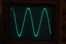
The curve form I see seems to be the "normal" today.
I wonder if a "heavy" lowpass filter could make it look closer to a real sinus.
I still have my MoFo chokes........
http://files.danfoss.com/download/Drives/DKDDPB14U301_EG_FC200.pdf
From page 15....
The curve form I see seems to be the "normal" today.
I wonder if a "heavy" lowpass filter could make it look closer to a real sinus.
I still have my MoFo chokes........
I think your problem of truncation in the AC is very difficult to solve with filters particularly not knowing what is riding over your mains freq. It would be quicker to see if others in your building have the problem and call the power company or move out! You have a DFT scope and attenuators to see what kind of frequencies you would have to filter out? You may need high pass and low pass. The principal 50 Hz frq is truncated so I imagine the fourier transform would huge sinc ring down around it. I don't know how the window function on scopes work. It is definitely saturating the core of your transformer and inducing the hum mechanical and dispersed flux like the Tony Stark arc reactor...LOL
I have written to the power company but I think sine waves like this is more and more normal caused by some strange asymmetrical loads on the network. Maybe something like this is needed:
Stellar Power Plant 3 | PS Audio
I wonder if some type of UPS (power no break) makes a nice sine wave. If they do they are probably expensive. Most probably makes a noisy sine.....if sine at all.
Stellar Power Plant 3 | PS Audio
I wonder if some type of UPS (power no break) makes a nice sine wave. If they do they are probably expensive. Most probably makes a noisy sine.....if sine at all.
The issue, most likely, is caused by reactive loads: air conditioners, refrigerators, well pumps, bench grinders, air compressors, sometimes even fluorescent transformers (large warehouses!!) can cause it.
You could try the following: if you have the column heaters (radiators), plug them all at various power outlets in the household and observer the waveform. if it becomes more of a proper waveform, you know it's the reactive load issue.
The solution is passive, or active filters (used at the point where distortion is introduced), that provide: harmonic mitigation, power factor correction, and load balancing. You may have some sort of manufacturing facilities that use 3 phase motors... these small manufacturing facilities are the worst because they routinely overlook the necessity of using the filters. This is where the electricity supplier has to step in.
The electricity supply has to confirm with few standards, one if which is: IEEE-519. If it does not, the electricity authority has to ensure that it does.
Last edited:
Is not normal, this is an electrical service issue on a massive scale. Unless your apartment building was wired by incompetent electricians which could make it an issue local to your building. If there is an imbalance in the phase loads it involves hundreds of houses and a serious issues with power management. Key distribution nodes in your area should have monitor facilities that redistribute the load and activate re-phasing capacitor banks that should come online as the waveform becomes as screwy as yours.
Power companies normally require large users to manage load distribution and impedance locally with capacitor banks to counteract the massive inductance from electrical motors so that all phases are loaded more or less equally and the load appear almost resistive.
Power companies normally require large users to manage load distribution and impedance locally with capacitor banks to counteract the massive inductance from electrical motors so that all phases are loaded more or less equally and the load appear almost resistive.
I have now some news. It seems the cut of the sine at the tops is normal caused by uneven current draw. E.g. our amps with rectifier has peak current at the top of sine and it will "cut them down". Maybe look at your own mains to confirm this. I live in a city and there are some meters of wire to the transformer station. So it probably depends of where you live how "ugly" the mains looks.
I have now invested in a small power re-generator which is made for audio (not an UPS). I now have a nice sine and my transformers are silent now. Ripple of rails has gone down from maybe 25mv AC to 0.0 mV when M2X are stabilized. The DC offset of the left mono block is 100% stable while the right channel is stable within -+ 30 mV or so.
I can see that the reason is the +DC rail varies from 22.25 to 22.45 VDC or so while the other is stable at -22.65 VDC. I can trace the variation down to after the first set of caps (it gets less and less "upstream"). AC secondary is 100% stable. I tested +DC rail with just a load resistor and here it is 100% stable. So PSU OK is my conclusion.
My next conclusion is that reason must be that M2X amp board varies a bit in load of positive rail while the negative load is stable.
Is that possible that upper mosfet goes a bit up and down in load (current draw)....and what can the reason be?
I had input grounded and speakers connected.
This is how my 230 VAC sine looks now and it is regulated.
Sound is fantastic. When DC-blocker arrives it will be mounted in front of re-generator.
It gives a dimension extra to the sound to have "clean" power.
I should probably not be too concerned that I can't reach same DC-offset stability in right mono block as the left. The left stays at 1mV.....but that is probably pure luck. But could be interesting to get an explanation. There can still be some "drift" even if AC mains is stabilized and temperature has stabilized. The last few hours it has been within +-20 mV.
Attachments
Yes, it is the smallest PS Audio power plant:
Stellar Power Plant 3 | PS Audio
It seems to fit perfect for the type of amps we do here. When you have a perfect regulated sine it is much easier to locate "problems" in the amp. I have a 230 VAC version. It has very low impedance (8 mOHm).
It has a couple of add-on features. A degauss function and a "sine" which has a bit of 3rd harmonic added to make the top of "sine" a bit wider to have more energy to charge the caps. I just use sine as rails drops 0.5 V or so when using the "Multi-wave" function. Tops gets wider but peak-to-Peak voltage drops slightly.
There seems to be two "religions" regarding this. PS-Audio and Audioquest. After "research" I like the PS-Audio approach much better.
I don't think I've seen this mentioned here – have you tried an LT4320-based synchronous rectifier? It might be less susceptible to less than perfect AC waveform.
I use some Cree Schottky diodes on the Universal PSU board. I am quite sure that the "dirty" sine caused the humming of the Toroid transformers as it disappeared when I got clean sine wave. Next is that it is easier for me to try to hunt down why one mono block can be stable within 1mV DC-offset while the other drifts a bit up and down. I have done a lot of measurements and with stable AC mains voltage I can compare what I measure and more easy see what change when DC offset gets "unstable".
What is interesting is that during my measurements suddenly amp was stable.....like my probes on resistors etc. had "cleaned something". Then I turned amp off and did some additional cleaning with Isopropanol. After I soldered the two mosfets I did not remove the flux. After I did that my rails was suddenly symmetric (-+ 22.64 V) after warmup and I could adjust offset down to 1mV precision. Then I did the same thing on other mono block which was stable but just to be sure. Then we will see.......
The unstable mono block had rails like -22.64 V and +22.25 to 22.55 V(fluctuating). In the moment it is stable. It is my assumption that fluctuating positive rail was due to uneven current draw and not bad connection (contact resistance etc.)
But now with stable AC I can continue measurements if problem should arise again.
I think DC on mains still "hunts" me. Will see which conclusion I can make after heavy DC-blocker are installed before re-generator. I was told it could be an good idea doing as large DC level can come through this small re-generator.
My trafo "humming" comes in "waves" with long period of silence and I can see that typical one rail goes a bit down during a "wave" and DC-offset raises during a "wave".
My trafo "humming" comes in "waves" with long period of silence and I can see that typical one rail goes a bit down during a "wave" and DC-offset raises during a "wave".
I might have found my error.
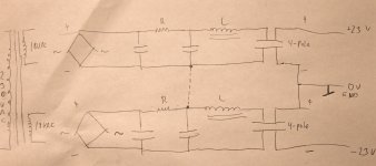
I attached a principle drawing of my PSU for each M2X mono block. It is based on the universal PCB (CRC) with and added LC filter where the C is a 4-pole capacitor and from this cap I define my Gnd. This connection also goes to chassis via a NTC.
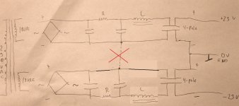
On the universal PCB I had soldered in one link between the two channels. It is the dotted line on schematic which I now have cut. It seems (we will see over time) this did the trick with both occasional slight humming from transformer and with one rail voltage 0.2-0.3 V lower then the other and going a bit up and down. And suddenly it could be stable.
Do you think the dotted line connection could have causes that (creating unbalance)?
I attached a principle drawing of my PSU for each M2X mono block. It is based on the universal PCB (CRC) with and added LC filter where the C is a 4-pole capacitor and from this cap I define my Gnd. This connection also goes to chassis via a NTC.
On the universal PCB I had soldered in one link between the two channels. It is the dotted line on schematic which I now have cut. It seems (we will see over time) this did the trick with both occasional slight humming from transformer and with one rail voltage 0.2-0.3 V lower then the other and going a bit up and down. And suddenly it could be stable.
Do you think the dotted line connection could have causes that (creating unbalance)?
Attachments
besides me being clueless what 4-pole cap is, that dotted line really can create all sorts of problems
GND need to be established on very end
GND need to be established on very end
A 4-pole cap is just a cap made for filtering only (not for coupling) which has two inputs and two output so DC current are flowing through the capacitor foils for better filtering.....is the theory.
After some hours now my left amp showing 0.6-0.8 mV of DC offset and right amp is showing 0.9 - 1.1 mV offset. And toriods are silent. I can hear a bit with ear close to it. The very stable DC offset is also caused by the regulated AC mains which is steady at 230.6 VAC or so.....with a nice sine.
After some hours now my left amp showing 0.6-0.8 mV of DC offset and right amp is showing 0.9 - 1.1 mV offset. And toriods are silent. I can hear a bit with ear close to it. The very stable DC offset is also caused by the regulated AC mains which is steady at 230.6 VAC or so.....with a nice sine.
What ZM said, though I’m familiar with 4-pole caps. The asymmetric nature of the circuit makes it more susceptible to ground loop issues. With your supply, the star ground needs to be in exactly one place, and should also include the speaker negative terminals.
Yes, that dotted line connection has been cut. It was a link on the Universal PCB between the two sections. I had only mounted one despite there are room for many 🙂 ...so I could cut it without unmounting the PCB board which has really many screws (used all mounting holes). I have one common star ground and very short wires from the 4-pole caps to the PCB (few cm). Electrical hum level was very low when I did REW measurement and I expect even lower level now.
- Home
- Amplifiers
- Pass Labs
- M2X strange DC offset and transformer noise problem