Don't forget that the J113 and 2SK170 have different pinouts.
If 2SK170 is a follower then 1 ma idss matching is adequate.
If 2SK170 is a follower then 1 ma idss matching is adequate.
Don't forget that the J113 and 2SK170 have different pinouts.
Thank you, I forgot to mention that. They were not hard to install, I used a magnifying glass to make sure the pins were not shorted together.
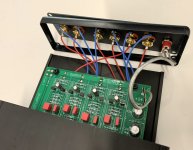

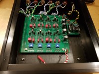
It is not that they are long, - it is that they are long enough for you to twist them - and then you should 😀Here is my LXmini ACV built, think the signal wires are a bit long.
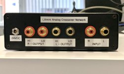
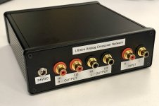
Looking great! - and fun to see the Mini ASP in the same box as the 521.x ASP
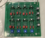
I built this LXmini crossover and measured DCs according to the LXmini crossover article.
These are guiding DCs
R47, R48, R49 ~ 0.5 V DC this will vary a bit, depending on the Jfets
R50, R51 ~ 11 V DC
R13, R14, R15, R16 ~ 0.7 V to ~1.0 V DC
R35, R36, R37, R38 ~ 0.7 V to ~1.0 V DC
R39, R40, R41, R42 ~ 0.0 V DC
R1, R2, R3, R4 R31, R32 ~ 12 V DC
... and I measured.
R47 (0.8), R48 (0.8), R49 (0.8) <= some high values
R50 (10.88), R51 (10.88)
R13 (1.46), R14 (1.45), R15 (1.48), R16 (1.47) <= some high values
R35 (1.36), R36 (1.45), R37 (1.48), R38 (1.46) <= some high values and R35 is little bit lower than others
R39 (0.003), R40 (0.003), R41 (0.000), R42 (0.001)
R1 (12.27), R2 (12.0), R3 (12.24), R4 (12.0), R31 (10.53), R32 (10.58)
Are these acceptable?
Attachments
Hey all. I have been MIA for a while with other projects. I'm wondering if the3 way LX-mini crossover project that NP hinted at in his original article for the analog crossover (for the LX-mini's). I am going to be using my minis as part of my HT system since I am downsizing and combing my 2 systems. Thanks! -T
I got a lot of pair 2SK246 and J103 BL grade. Someone can give some advices, is it possible to do it with my JFETs ?

yes, no changes
you'll just have slightly higher Rout, due to lower xconductance vs. originally used
you'll just have slightly higher Rout, due to lower xconductance vs. originally used
always you 🙂 , thank you.
maybe we need a buffer like B1 after XO.
my system: LOW will be put my BA3 - DEF amp, and HI will be next B1-THF single end amp.
Wonderful christmas time. ha 😀
maybe we need a buffer like B1 after XO.
my system: LOW will be put my BA3 - DEF amp, and HI will be next B1-THF single end amp.
Wonderful christmas time. ha 😀
you're good, no need for additional buffers
I mean - try, if you like it, you know what to do
use best PSU you can think of, it always pays off
I mean - try, if you like it, you know what to do
use best PSU you can think of, it always pays off
NP "You mean the Lxminis plus sub?"
My10 year old minidsp just died and is no longer supported. I would prefer to replace it with the analog unit if it is likely to become available any time soon -
3 way including dipole subs.
Thanks
My10 year old minidsp just died and is no longer supported. I would prefer to replace it with the analog unit if it is likely to become available any time soon -
3 way including dipole subs.
Thanks
I built this xover 3 years ago. Wonder that suddenly the Low frequency output volume in one channel is much lower than in the other.
So, what part in that section would be likely compromised in your opinion?
And I can order a new kit and built it.
Thanks for looking
So, what part in that section would be likely compromised in your opinion?
And I can order a new kit and built it.
Thanks for looking
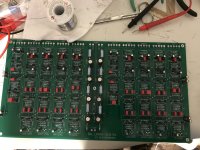
There is a kit here: https://linkwitz.store/product/asp-lxmini2-nelson-pass/. Here is a photo of my PCB build.NP "You mean the Lxminis plus sub?"
My10 year old minidsp just died and is no longer supported. I would prefer to replace it with the analog unit if it is likely to become available any time soon -
3 way including dipole subs.
Thanks
Attachments
Low frequency output volume in one channel is much lower than in the other.
I think the first part to check would be the 25K input pot. After that, look for poor solder connections on that channels Low freq. circuit.
Please post pictures of your crossover, both sides of the PCB, this will help others give you better advise than mine.
- Home
- Amplifiers
- Pass Labs
- LX-mini Crossover Article