Forgive me for the noob question but I'm after an active crossover with no eq. Would the ACN be configurable for this?
Hi Nelson,
Today I watch the BAF2017 video, in which you provided information about crossover network for LXmini+2. From this video, I see you have provided the EQ section in addition to low pass filter for subwoofer module, but this EQ section is omitted in the ASP board for LXmini+2 in magiclx521. Could you provide me the reason why you do that?
Thanks,
Trung
The bass section of the LXmini requires a bass boost, thus the EQ, but in the +2
version that need is filled by the subwoofer, leaving only the EQ on the top driver.
version that need is filled by the subwoofer, leaving only the EQ on the top driver.
Hi Nelson,
Thanks for your answer but I talk about the LXmini+2 (3 ways) crossover, schematic in time of 39:29 in the video of your presentation Burning Amp 2017.
YouTube
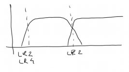
I see for Subwoofer section there are two LR2 low pass filters in the schematic in series with a filter module , which I think it is an EQ or bass equalization. In the final PCB (on magiclx521 website), the EQ/bass equalization has been omitted, leaving only the two LR2 low pass filters. So I would like to ask why you do that.
Thanks for your answer but I talk about the LXmini+2 (3 ways) crossover, schematic in time of 39:29 in the video of your presentation Burning Amp 2017.
YouTube
I see for Subwoofer section there are two LR2 low pass filters in the schematic in series with a filter module , which I think it is an EQ or bass equalization. In the final PCB (on magiclx521 website), the EQ/bass equalization has been omitted, leaving only the two LR2 low pass filters. So I would like to ask why you do that.
I see for Subwoofer section there are two LR2 low pass filters in the schematic in series with a filter module , which I think it is an EQ or bass equalization. In the final PCB (on magiclx521 website), the EQ/bass equalization has been omitted, leaving only the two LR2 low pass filters. So I would like to ask why you do that.
The filter set at BAF 2017 was an initial design for the +2 version, and
included a bass boost EQ circuit as used in the LXmini. Later in 2018
Siegfried decided to omit the bass boost on the +2 and S versions,
but it is still included in the LXmini circuits.
Hi...
At the moment I'm using DSP to set my crossover points but would like to have back up plan.
I need simple LR 2 order in be twin midbass and tweeter (around 2kHz) and LR 2 or 4 order on lower part of midbass (at 100-200Hz).
Any one have idea how many PCB do I need to get those crossover points in balanced (XLR) configuration ?
(I presume that I would need 4 PCBs)
Thanks
Attachments
Yes, 4 single-ended stereo boards with hi pass and low pass would do it.
Thank you 😀
Papa, care to comment on BF862?
https://www.diyaudio.com/forums/pass-labs/254190-options-5-integrated-amp-3.html#post6163092
edit: Sorry just saw that it has been discontinued; so probably late to get an opinion on.
BF862 is now End Of Life. Well that sucks. | Details | Hackaday.io
https://www.diyaudio.com/forums/pass-labs/254190-options-5-integrated-amp-3.html#post6163092
edit: Sorry just saw that it has been discontinued; so probably late to get an opinion on.
BF862 is now End Of Life. Well that sucks. | Details | Hackaday.io
Last edited:

Hi lovely DIYers,
Not sure if this is the right place for this question, but someone may have hit the same pothole?
I want to configure the ACN for a bass / full range combo with a crossover somewhere around 120 Hz.
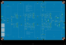
I've downloaded LT Spice and the ASCII file for the LX Mini crossover on a Mac desktop running macOS 10.13.6. I can get the sim working (yay!), but when I try to edit values I get this:
https://www.diyaudio.com/forums/attachment.php?attachmentid=835755&stc=1&d=1587331936
And nowhere an option to actually edit values. I've tried editing the ASCII file (no cigar). I've tried LT Spice help. I've tried deleting and reinstalling LT Spice, deleting and re-downloading the ASCII file.
Any help greatly appreciated!
Not sure if this is the right place for this question, but someone may have hit the same pothole?
I want to configure the ACN for a bass / full range combo with a crossover somewhere around 120 Hz.
I've downloaded LT Spice and the ASCII file for the LX Mini crossover on a Mac desktop running macOS 10.13.6. I can get the sim working (yay!), but when I try to edit values I get this:
https://www.diyaudio.com/forums/attachment.php?attachmentid=835755&stc=1&d=1587331936
And nowhere an option to actually edit values. I've tried editing the ASCII file (no cigar). I've tried LT Spice help. I've tried deleting and reinstalling LT Spice, deleting and re-downloading the ASCII file.
Any help greatly appreciated!
Attachments

24db/octave lr
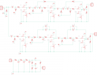
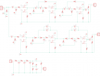
Here is a 24db / octave based loosely 😀 on the lxmini with 2sk170 loaded by the j113. Any thoughts?
Here is a 24db / octave based loosely 😀 on the lxmini with 2sk170 loaded by the j113. Any thoughts?
Attachments
Nelson, could I please trouble you to put forward an all pass phase shift fet based filter for time alignment use, to go with the lp & hp filters you've already done?
Here is a 24db / octave based loosely 😀 on the lxmini with 2sk170 loaded by the j113. Any thoughts?
You have what appears to be unnecessary DC blocking caps at the
output of the filters. In my experience you can arrange for sufficiently
low DC shift on each stage that you can get away with just the one
at the main output. Selecting the J113's and their Source resistance
will also allow fixed resistors instead of pots.
Nelson, could I please trouble you to put forward an all pass phase shift fet based filter for time alignment use, to go with the lp & hp filters you've already done?
Siegfried did not specify a phase shift filter for the LXmini and sub versions.
You can get information on all pass filters by entering that phrase on
Google and it will take you straight to Wikipedia.
And you can make your own op amps if you want discrete:
http://www.firstwatt.com/pdf/art_diy_opamp.pdf
Thank you for your reply.
My interest is outside the LXmini application, specifically a Tannoy dual concentric driver, which always benefit from time alignment given the mechanical arrangement between the lf and hf parts of the driver.
My enquiry was based on wanting to maintain the electronic flavour of your design, if that is a valid descriptor, on the all pass filters to go with your main filter board set that's already on its way here.
You have what appears to be unnecessary DC blocking caps at the
output of the filters. In my experience you can arrange for sufficiently
low DC shift on each stage that you can get away with just the one
at the main output. Selecting the J113's and their Source resistance
will also allow fixed resistors instead of pots.
OK, I think this is what you were describing. I realized I didn't have it labeled on the original schematic, but this would be using 2sk170s loaded by the j113s. the 2sk170s and the j113s are matched, so i suppose need to set up a jig with a pot and determine the value of the load resistor. Or would loading the 2sk170 with a j113 require the coupling caps? Thanks for the help.
Attachments
Usually you want to run the 2SK170's at slightly less than their Idss, which
gives them a slight DC offset, but not enough to create problems as long
as there is a cap at the end of the chain of circuits.
You can run them at Idss if you want, the difference is subtle.
Most of the J113's have higher Idss, so you would pick a resistor value
which biases them at the figure desired for the 2SK170's.
- Home
- Amplifiers
- Pass Labs
- LX-mini Crossover Article