OK, great. So no venting required.Mainly passing it along. Only a few Watts dissipated as wire resistance and core losses.
Thanks for all of your help!
YOU HAVE TO OPEN THE BOTTOM PLATE OF THE THE LUXMAN. THERE YOU WILL FIND IT IS SET FOR 100V YOU HAVE TO MOVE THE JUMPER TO 115V FOR INPUT VOLTAGE. ALSO YOU NEED TO DO THIS.
If you look at the two plugs near the bottom,the violet and blue need to swap position and the red and orange on the plug next to it also need to swap.The blue and red are 100 volt taps.And the violet and orange are the 115 volt tap
If you look at the two plugs near the bottom,the violet and blue need to swap position and the red and orange on the plug next to it also need to swap.The blue and red are 100 volt taps.And the violet and orange are the 115 volt tap

I am putting together a Digikey order and about to buy the bucking transformer. @renjy651 thanks for your reply.
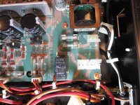
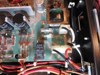
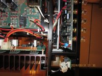
I pulled the bottom plate. It looks like this is a straight 100v product in the configuration that I bought it.
The black and white plug is the 100v power in. It goes directly to the small transformer through the 100 mA fuse and then to the black and red plug via the 12A fuse.
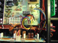
I traced the black and red wires and they go directly to the big transformer in the third picture where marked with a red arrow.
So I assume that I go with the bucking transformer which looks pretty easy to wire in.
I pulled the bottom plate. It looks like this is a straight 100v product in the configuration that I bought it.
The black and white plug is the 100v power in. It goes directly to the small transformer through the 100 mA fuse and then to the black and red plug via the 12A fuse.
I traced the black and red wires and they go directly to the big transformer in the third picture where marked with a red arrow.
So I assume that I go with the bucking transformer which looks pretty easy to wire in.
Attachments

WHICH LUXMAN IS THIS UNIT? LUXMAN L-505U AND THE NEWER LUXMAN L-505UX SERIES ARE DIFFRENT.
HERE IS LUXMAN LUXMAN L-505U 100V JAPAN VOLTAGE THAT I CHANGED TO USA 115V. THAT BLACK WIRE ON TOP WAS SET AT 100V ON PICTURE 2 FOR JAPAN 100V (136(5) JPG MOVE THAT TO 115V ON PICTURE 1 IS THE 115V OPERATION DSC00144,
FOR 230V YOU HAVE TO CHANGE FUSES AND MOVE IT FROM 110/115V TO 230V OPERATION.
HERE IS LUXMAN LUXMAN L-505U 100V JAPAN VOLTAGE THAT I CHANGED TO USA 115V. THAT BLACK WIRE ON TOP WAS SET AT 100V ON PICTURE 2 FOR JAPAN 100V (136(5) JPG MOVE THAT TO 115V ON PICTURE 1 IS THE 115V OPERATION DSC00144,
FOR 230V YOU HAVE TO CHANGE FUSES AND MOVE IT FROM 110/115V TO 230V OPERATION.
Attachments
Mine is a L-550AX. Not the 'II' version.
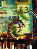
I see the jumpers on your power supply. I have musical Fidelity gear with similar jumpers and I was hoping that this was the case here when I bought the unit, but I do not see the jumpers.
I see the jumpers on your power supply. I have musical Fidelity gear with similar jumpers and I was hoping that this was the case here when I bought the unit, but I do not see the jumpers.
In reading the Rod Elliot article above, the standard way or wiring the bucking transformer is 'Figure 3' and a better way per Elliot is 'Figure 4.' I have marked the Figures using the Triad F7-20 transformer in the attached.
Is this correct? I want to use the Figure 4 configuration as he said that it has less losses.
Sorry for the newbie questions, I was a civil engineer, not an EE so...
Attachments
You got this totally wrong.It goes directly to the small transformer through the 100 mA fuse and then to the black and red plug via the 12A fuse.
The small transformer is only for the st. by function., making a 6 to 12ish small DC to make you able to switch between st. by and ON on your remote control.
The power on (mains to big transformer) is done through the relay next to the power inlet.
As others have said: Stick to the external, or buy the correct power- and st. by transformer for your mains.
Hi @TWKhorn
Either figure 3 or figure 4 will work fine.
Figure 3 is the same as my sketch in post 16, and Elliot's arrangement in figure 4 had never occurred to me. The figure 4 voltages are incorrect however. I estimate the delivered voltage is about 102V rather than 99V; the explanation is that the primary is driven with only 102 VAC rather than 120V. Consequently, the buck winding produces fewer volts, resulting in larger net output.
You can test as an outboard convertor to confirm they're no surprises before attempting interior install.
Happy Independence Day!
HI,
BECAUSE 230V SLOT HAS HOLES NO CONNECTORS TO CHANGE TO 230V. USE A NISSYO NDF-1500U JAPAN MADE TRANSFORMER 115V TO 100V STEP DOWN TRANSFORMER NEVER USE TRANSFORMER MADE IN CHINA. LOOKING AT MY LUXMAN L-505U If you look at the two plugs near the bottom,the violet and blue need to swap position and the red and orange on the plug next to it also need to swap.The blue and red are 100 volt taps.And the violet and orange are the 115 volt tap
I AM NOT SEEING THOSE WIRES TO SWAP ON 550AX. ALSO I SEE RED CHINA MADE PARTS? 505U AND 507U 509U ALL JAPAN AND USA MADE PARTS.
ONLY LUXMAN HAS THE BLACK WIRES TO MOVE THE INPUT VOLTAGE IS L-505U L-507U L550A. THOSE UNITS LOOK LIKE MINE EVEN THE NEW ONES IF YOU HAVE 110/115V 230V CONNECTORS YOU CAN SWAP THE WIRES . THE BLACK WIRE ONLY ON U SERIES. BE VERY CAREFUL IF YOU MAKE A MISTAKE SCHOTSKY DIODES WILL BLOW IN THE BOARD.
THANKS
TWKhorn
LOOKING AT YOUR L-550AX POWER SUPPLY IT IS DESIGNED FOR JAPAN 100V ONLY.BECAUSE 230V SLOT HAS HOLES NO CONNECTORS TO CHANGE TO 230V. USE A NISSYO NDF-1500U JAPAN MADE TRANSFORMER 115V TO 100V STEP DOWN TRANSFORMER NEVER USE TRANSFORMER MADE IN CHINA. LOOKING AT MY LUXMAN L-505U If you look at the two plugs near the bottom,the violet and blue need to swap position and the red and orange on the plug next to it also need to swap.The blue and red are 100 volt taps.And the violet and orange are the 115 volt tap
I AM NOT SEEING THOSE WIRES TO SWAP ON 550AX. ALSO I SEE RED CHINA MADE PARTS? 505U AND 507U 509U ALL JAPAN AND USA MADE PARTS.
ONLY LUXMAN HAS THE BLACK WIRES TO MOVE THE INPUT VOLTAGE IS L-505U L-507U L550A. THOSE UNITS LOOK LIKE MINE EVEN THE NEW ONES IF YOU HAVE 110/115V 230V CONNECTORS YOU CAN SWAP THE WIRES . THE BLACK WIRE ONLY ON U SERIES. BE VERY CAREFUL IF YOU MAKE A MISTAKE SCHOTSKY DIODES WILL BLOW IN THE BOARD.
THANKS
Yes, you are correct. I should have said 'and also to' the big transformer.You got this totally wrong.
The small transformer is only for the st. by function., making a 6 to 12ish small DC to make you able to switch between st. by and ON on your remote control.
The power on (mains to big transformer) is done through the relay next to the power inlet.
As others have said: Stick to the external, or buy the correct power- and st. by transformer for your mains.
Thanks, would you go with the 99v or 102v configuration? My power is typically about 119v to 122v per my power conditioner.Hi @TWKhorn
Either figure 3 or figure 4 will work fine.
Figure 3 is the same as my sketch in post 16, and Elliot's arrangement in figure 4 had never occurred to me. The figure 4 voltages are incorrect however. I estimate the delivered voltage is about 102V rather than 99V; the explanation is that the primary is driven with only 102 VAC rather than 120V. Consequently, the buck winding produces fewer volts, resulting in larger net output.
You can test as an outboard convertor to confirm they're no surprises before attempting interior install.
Happy Independence Day!
I did see the Made in China parts and thought that it was a little strange. They are hidden on the bottom. Can this be a grey market unit? It seems really well built.
I guess I'd be inclined to the Elliot configuration. It gives modestly larger delivered AC to the LUX and hence very slightly more available available power/headroom.
Enjoy!
Enjoy!
Ok, I finished another project and I am now trying to install the Triad bucking transformer. The Luxman has an IEC connector mounted upside down. Being Japanese it does not have a ground wire. The Luxman power cord is beautiful looking, but it is two prong, not three. I want to wire this for use in the USA with any power cord so two issues came up.
In a nutshell, it looks like in Japan they wire their Type A outlets backwards and use the long pron for (N) and the shorter prong for (+).
1. See the photo below that I took upside down to make this easier. The IEC receptacle on the back of the Luxman is upside down. If I use a USA cord, the 'N' prong on the left that corresponds to the long outlet female on the left is the black wire inside of the Luxman, and the right wire is white.
I just want to make sure that I am correct as it seems that I need to use the white wire inside the unit for (+) to the bucking transformer and the black wire inside the unit for (N) to the bucking trasnformer. I took a second photo with the pigtail from the wire inside of the Luxman where I will splice in some wire and extend to the bucking transformer. You can see the black wire going to two fuses, one high amp (12A) for the big trasnformer inside of the amp and one low amperage (100ma) into a small trasnsformer for the other electronics in the amp.
I know this is a very easy question, but it just feels strange wiring the black to (N) and White to (+).
1. Should I add a ground to chassis from the third prong? Seems like a good idea as I want to wire this to use any IEC compatible cord.
Thanks and sorry for such a simple question.
Attachments

Threads like these should be banned. In general and not to offend as it is about electrical/fire safety: people that tighten bolts CCW import stuff from other countries and often don't know jack about electrical safety or regulations of the country where they bought the device nor of their own country. This means units are modified, bucking transformers are suggested by members here that do have a clue etc. Rarely the final result is showed to the ones that gave advice to see if things have been done correctly/safe. Folks, you are giving advices to work on the mains side of things to laymen!!
Now we see a suggestion to have a class II unit converted to class I. It is certainly not meant to be like that. And mains voltage IEC inlets do not have a +!
IMHO just obtain stuff where you live and stay safe. Keep it simple and safe, also for the ones around you and the possible owners of that device in the future. If you have the knowledge then you won't need to ask every detail and you would know how things are called.
Last edited:

Seeing that concerns over safety have been raised with the moderation team we would first draw everyone's attention to the site rules and terms and conditions which state:
2. Your safety and the safety of others. While most projects on this site deal with electricity and construction which inherently involve some risk, particularly dangerous topics and procedures should include a warning in the thread that adequately explains these risks. The forum itself is not in the business of vetting projects or posts for safety, accuracy, performance, reliability, function, or fitness for use. If you attempt to make something and it blows up, or turns expensive parts into charcoal, or just doesn’t work the way you were hoping, that’s between you and the person posting the project or idea. The forum is merely a bulletin board which allows anyone to post ideas, criticisms, or discussions. It is up to the individual to make the final determination of how appropriate a project is for them to attempt, based on their own experience.
@TWKhorn if you are not confident or sure in your abilities with this project then the only recommended course of action is to not proceed.
If the amp is originally Class II (double insulated) and you fit a second transformer internally to use a bucking coil and/or alter the internal mains wiring (or indeed anything) in any way then that Class II status becomes invalid as possible safety hazards and implications have been introduced. For example what if the second transformer exhibits leakage or a fault to its metal frame?
In the case of modifying an amp in this way using the amp with a proper 3 core grounded mains lead suitably attached to the chassis such that it can carry the full current any fault can cause is then mandatory. Even doing this does not ensure guaranteed safety under all possible conditions with that depending on the physical construction and design of the amp. For example external metal parts in a double insulated amp that are not connected to chassis or that would not carry a fault current if they were involved in a failure. These could still become live 'if something touched something' without blowing the fuse.
If you are not sure in your own mind something is 100% safe then don't risk it. Shock and fire hazards are just not worth it.
Threads like these should be banned. In general and not to offend as it is about electrical/fire safety: people that tighten bolts CCW import stuff from other countries and often don't know jack about electrical safety or regulations of the country where they bought the device nor of their own country. This means units are modified, bucking transformers are suggested by members here that do have a clue etc. Rarely the final result is showed to the ones that gave advice to see if things have been done correctly/safe. Folks, you are giving advices to work on the mains side of things to laymen!!
Now we see a suggestion to have a class II unit converted to class I. It is certainly not meant to be like that. And mains voltage IEC inlets do not have a +!
IMHO just obtain stuff where you live and stay safe. Keep it simple and safe, also for the ones around you and the possible owners of that device in the future. If you have the knowledge then you won't need to ask every detail and you would know how things are called.
I think jean-paul is channeling Dirty Harry: "A man's got to know his limitations." Can't quarrel with that.😉
I appreciate the concern offered. This is, by name literally, a DIY forum in which members wish to learn and extend themselves. It goes without saying they need to proceed safely.
Best.
Gentlemen, thank you for the input. I bought the Luxman locally and didn't know if was a Japanese spec until I showed up. I thought that it would be a simple wire and fuse swap as in some other US gear that I have that can swap to Euro very easily. So here I am owning this thing.
I was a engineer 20 years ago but definitely the wrong kind as you can see by my questions.
So to boil this down, is there a safe way to add the Triad bucking transformer inside of the compartment in the Luxman? If not, I will just use an outboard transformer that has a good safety margin.
I cannot tell if the Triad F7 transformer is Class II. It is not marked nor does it have the double box symbol, but it is UL Recognized so I think a manufacturer would put the symbol on the end product.
If I cannot use the Triad inside of the Luxman, can I mount it in a grounded box or a plastic enclosure outside of the Luxman?
- Home
- Amplifiers
- Solid State
- Luxman L-550 AX voltage change 100v to 120v