Hi experts,
I am repairing Luxman L-100. There are two driver circuits L649 for each channel driving the power transistors. A power supply that is 55 volts DC feeding to these circuits. When I pull up the connector of one channel supply, Left Channel or Right channel it works only that channel which has power supply but once I put connector of both channels, front light keep on flashing. Only one channel at a time. If anybody guide me, I will be thankful to you. Waiting for comments from experts.
Yes, I swap both Channel's power stage but behaviour of amp remains same. This is clearance indication that something wrong with the power supply. It has not enough power to drive two channels together.

If you don't have a schematic is can be pretty hard to figure out. Sometimes hi-res pics will help facilitate visual inspection by some experienced people.
Thanks Mark
I downloaded schematics of L-100 from internet and then compare with PCB all resistances have same value even second check matched with color coding. All transistors were checked and we're giving 0.5 volts voltage drop on fluke meter. Same is for diodes. Base-Emitter 0.5 then Base to Collector 0.5 for all pnp & npn transistors. Revered biased open. All components seems ok. May be relay or dry solder. Behaviour is no erratic but fixed pattern.
Downloaded schematics from service manual are not of a good quality. I was ready to purchase proper manual but could not. I think I have to work more in finding the fault. All components were tested in board.
What I found the service manual is not of a high standards rather confusing.
Attachments

If that's the one, it will probably do well enough.
Then the next question would be if you have an oscilloscope?
Then the next question would be if you have an oscilloscope?
Yes. I have Oscilloscope. Spectrum analyser, FFT, Signal Generator, Bench top power supplies. I mean complete lab.
Go to page no 16 of service manual and then find the component details of PB-649. You will not find the list of transistors used. I mean in complete. Next two resistance in power supply PCB are given the value 68 ohms but actually these are 1.0k. I measured with meter and through color code. Resistance has the color code brown- red-black. 10*100*1=1k but service manual is giving 68 ohms. So the document that shared is not reliable. There are few more mistakes in document.
Well, if everything checks out ok with offline tests, and with power-on DVM measurements, then the next step might be to start with some signal tracing and signal analysis type of troubleshooting. What do you think?
Dear Mark
Thanks for the suggestion to check the signals but I think fault is in power supply. Let me trace the voltage then conclude.
Thanks for the suggestion to check the signals but I think fault is in power supply. Let me trace the voltage then conclude.
Today I tested the power supply voltage are ok. It gives +- 58 volts on both side of connectors. This +- DC is directly coming from two main filter capacitors. (Linking to Bridge Rectifier). If I hook left channel power supply connector with PCB 649 then front light blinks & relay gets ON while right channel un hooked.
Similarly if I connect right channel power supply and left un hooked same happend front light blinks then relay gets ON but if I hook both left & right connectors as per it should be then lights keep on blink and relay does not gets ON.
Now please help me what should I do next. Should I test all transistors and diodes of power amplifier then power supply control board.
So, to recap the symptom, a light comes on unless you pull a connector somewhere. So, which connectors on the schematic are you pulling? And which light on the schematic are we talking about?
It would be helpful for people reading along who might be able to help if you post a pic of the schematic where the connectors you are disconnecting are circled in red or something like. Also, if you can find the red light on the schematic then circle that area in red.
Then we know where in the circuitry you are talking about. Makes it much easier for us to analyze the circuits faster.
Hi
I make video of what I am doing and attach as a file here. Then one will understand quickly. I don't know if forum allows video or not. I will try to attach, if not then from schematic I will make circle as you told me.
I make video of what I am doing and attach as a file here. Then one will understand quickly. I don't know if forum allows video or not. I will try to attach, if not then from schematic I will make circle as you told me.
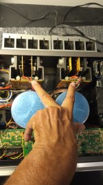
Above are two connectors. One is power supply of left Channel and other is for right channel. If I unplug any of it. Relays ON.
Circuit diagram is not complete.
Circuit diagram is not complete.
Okay. Do those connectors carry any of the signals shown in the red outlined area below?

If so, which signals are they? If not, which signals on the schematic are you disconnecting?
If so, which signals are they? If not, which signals on the schematic are you disconnecting?
I removed all the following power transistors from bases and just tested and find them ok.
Q421, 422, 423, 431, 432,433 (TO-3) Fluke meter was used. No leaky no problem base-emitter, base-collector are perfect and then emitter-collector, no leakage.
Q421, 422, 423, 431, 432,433 (TO-3) Fluke meter was used. No leaky no problem base-emitter, base-collector are perfect and then emitter-collector, no leakage.
- Home
- Amplifiers
- Solid State
- Luxman L-100