L-100 was in production when - end of 70-ies?Many amplifiers require a power reset if a safety circuit trips.
Name some other amplifiers of that era with that sort of "protection".
I think this protection is for speakers. If DC level increased in power stage and going directly to speakers, it is of course very harmful to woofers and amp power transistors as well. Nakamichi amp designer used crowbar protection to protect speakers instead protection relay turns OFF due to DC oscillations develop due to over crank the volume. I think clipping of Amp over certain limits turning the sine wave into DC level. It is just my apprehension not from the main stream designer of amps.99% of commercial amplifiers are sold without that kind of "protection" - correct?
Are the speaker protection relays not installed for that purpose?If DC level increased in power stage and going directly to speakers,
Or L-100 does not have one?
Don't see what that has to do with it? Maybe it was the first? If so, why should it matter?Name some other amplifiers of that era with that sort of "protection".
Anyway if you want to redesign your own L-100, nobody will object.
You bet, and it would not have any internally generated power failures.if you want to redesign your own L-100, nobody will object.
Some things tried out have proven failures during the life cycle of the product line.Maybe it was the first? If so, why should it matter?
Looks very much like one of these.
There are two relays one in power supply and other is in preamp, I don't know why two, more the components more will be the distortion because of thermal noise of individual component circuitry should be simple with minimal components will be better. Luxman L-100 is very cowdy with parts. Mute function is another complexity. Tone control seems very complex.Are the speaker protection relays not installed for that purpose?
Or L-100 does not have one?
As I already told that I am not expert of audio amps but understand electronics as an engineer. Only few amps I repaired.
Haven't looked at it, but some tone controls may include loudness compensation. If implemented, its to provide more bass at lower volume levels for Fletcher-Munson compensation.Tone control seems very complex.
https://en.wikipedia.org/wiki/Equal-loudness_contour
Tone control design could be for something else too. There are various types of tone control circuits.
Ok, to sum it up - it is not my amp and I have never worked on it. But if it does not have the speaker protection relay and speaker protection is implemented by this kind of power "protection" then I would just install a speaker protection relay module and remove all fancy stuff from the power lines making them simple, robust and reliable.There are two relays one in power supply and other is in preamp,

I am not going to redesign power supply it was my idea and I was only seeking expert suggestions. I respect your opinion about matching of power supply with pre & power amps and accepted it. It is because I am not expert of designing audio amps. My experience is in motor control, power electronics for industry at system & sub system level.You bet, and it would not have any internally generated power failures.
The Bose speaker ( Bose 901) manufacture once used active equaliser which was must to bring in between Source & Amplifier which boost only certain low frequencies and also middle frequencies. I think it was active crossover and do same action with sound.Haven't looked at it, but some tone controls may include loudness compensation. If implemented, its to provide more bass at lower volume levels for Fletcher-Munson compensation.
In the newer models of the L100, the startup circuit on board P647 has been removed. On these modified models, the power supply on board P647 is powered op by two diodes mounted on the back of board P649.
Do a Google search for L100 restoration and Flickr has a repair report with 100 photos, where you can see the two diodes mounted on board P649.
Do a Google search for L100 restoration and Flickr has a repair report with 100 photos, where you can see the two diodes mounted on board P649.
Thanks for it. I downloaded all photos but unable to find diodes on the back side PB-647 power supply. Can i try to bypass the startup circuit by adding some bias voltage to the base of any suitable transistor on PB-647 with trim pot.Do a Google search for L100 restoration and Flickr has a repair report with 100 photos, where you can see the two diodes mounted on board P649.
The idea is that in normal operation the power supply reference zeners are powered from clean power on the regulated side. So long as that feature remains intact, an alternative startup circuit is probably okay.
There are other approaches to producing a stable zener reference too, such as taking power from the unregulated side, filtering it, then using the filtered power to drive a current source to bias on the zeners with a very stable current. That said, the is some other circuitry connected between the zeners which should analyzed first before any major changes to zener biasing. Might not be any problem, but reasonable to take a look at it.
There are other approaches to producing a stable zener reference too, such as taking power from the unregulated side, filtering it, then using the filtered power to drive a current source to bias on the zeners with a very stable current. That said, the is some other circuitry connected between the zeners which should analyzed first before any major changes to zener biasing. Might not be any problem, but reasonable to take a look at it.
Last edited:
In order to carry out repairs on these amplifiers, it is important to at least use a dim bulb tester as a current limiter in case there is a short somewhere.
Please see attachmentThe two startup diodes are mounted on the back of board P649.
Please see attachment. Picture of PB647 board. Encircles there are only two transistors bases.The two startup diodes are mounted on the back of board P649.
Attachments
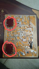
Two zener diodes Plus voltage (24+24=48) ( for driver stage)The two startup diodes are mounted on the back of board P649.
On board PB649
Two zener diodes minus voltage (-24-24=-48) ( for driver stage) on board PB649
Please guide reference ground will be common with power stage ground. I hope it should be common for both stages, driver & power stage.
Both the diodes are on the component side. See attachment
The two startup diodes are mounted on the back of board P649.
Attachments
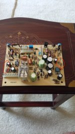
I am already using 200 watts bulb in series for over current protection. If use 100 watts bulb then capacitor charging will take more time to fully get charge and has to wait longer after switch ON the amplifier. See attachment.In order to carry out repairs on these amplifiers, it is important to at least use a dim bulb tester as a current limiter in case there is a short somewhere.
Attachments

Gentlemen,
Since nobody has found information on how to modify startup circuit on this particular amplifier, I would suggest that idea be abandoned and we return to troubleshooting.
Most of the problems with these amplifiers are known to be due to bad electrolytic capacitors. Also, there is a troubleshooting procedure to start up the power supplies using a 4.7k resistor. Has that procedure been tried yet? If so, what was the result?
Have the electrolytic capacitors ever been replaced in this unit?
In particular, has the startup electrolytic capacitor been replaced recently?
These are basic questions that will lead to the next troubleshooting step, if further steps turn out to be needed.
- Home
- Amplifiers
- Solid State
- Luxman L-100