21v trafo will be about 25vdc after SLB 3v drop from cap multiplier and 2v drop from voltage sag due to 3A class A load.
3A x 25v is 75W thermal dissipation per channel x 2 channels is 150W not including dissipation in SLB.
That’s running at about 50%+ capacity for the trafo. 400VA would be better in my opinion.
3A x 25v is 75W thermal dissipation per channel x 2 channels is 150W not including dissipation in SLB.
That’s running at about 50%+ capacity for the trafo. 400VA would be better in my opinion.
No I only have this amp on and Iḿ listening with my phone.And when Iḿ turning it off the beep goes lower in frekvensy until it dissapeares.It could also be from a PSU from another of your amps?
So it must be the SMPS.
I ordered 2 SLB singel rail pcb,where do I get the BOM?
I will try to use 400VA 23v dual secondary or two 200VA 23V single secondary with SLB single rail PCBs.
23 * 1.4 - SLB dropout(about 2V) - sag with load(about 2V) = 28VDC supply for single rail I guess.
Tungten Audio's SLB PSU build with seperate chassis seems so great. (https://www.diyaudio.com/community/threads/diy-sony-vfet-builders-thread.370689/post-6685621)
23 * 1.4 - SLB dropout(about 2V) - sag with load(about 2V) = 28VDC supply for single rail I guess.
Tungten Audio's SLB PSU build with seperate chassis seems so great. (https://www.diyaudio.com/community/threads/diy-sony-vfet-builders-thread.370689/post-6685621)
That is a very raw guess, depending on several factors.
Best is to calculate the output impedance of the amp by measuring loaded vs unloaded output voltages (you can find somewhere how to).
Damping factor is loudspeaker load impedance divided by amplifier output impedance, so it depends on the load (typically two times higher at 8 ohm load vs 4 ohm load).
I have no knowledge about measuring Vds, bias etc.
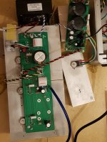
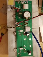
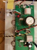
The power voltage is 30V from single rail SLB and 400VA trans without load.
I'm using curve tracing matched LUs from @mbrennwa.
I using 300x150x75 heatsink per channel for testing.
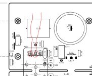
There are test points on pcb.
What voltage range between these test points is acceptable ?
P102 - P108
P104 - P108
P106 - P108
Is R101 trimpot for adjusting bias?
How can I check bias?
Is R184 trimpot for adjusting Vds of LU?
How can I check Vds?
What Vds range is acceptable?
The power voltage is 30V from single rail SLB and 400VA trans without load.
I'm using curve tracing matched LUs from @mbrennwa.
I using 300x150x75 heatsink per channel for testing.
There are test points on pcb.
What voltage range between these test points is acceptable ?
P102 - P108
P104 - P108
P106 - P108
Is R101 trimpot for adjusting bias?
How can I check bias?
Is R184 trimpot for adjusting Vds of LU?
How can I check Vds?
What Vds range is acceptable?
DC offset : 1.78V
some wrong.
I measured the voltage drain - source pin with two leads of voltmeter directly, and it shows me 0.09 ~ 0.16V wiggling.
some wrong.
I measured the voltage drain - source pin with two leads of voltmeter directly, and it shows me 0.09 ~ 0.16V wiggling.
Attachments
Last edited:
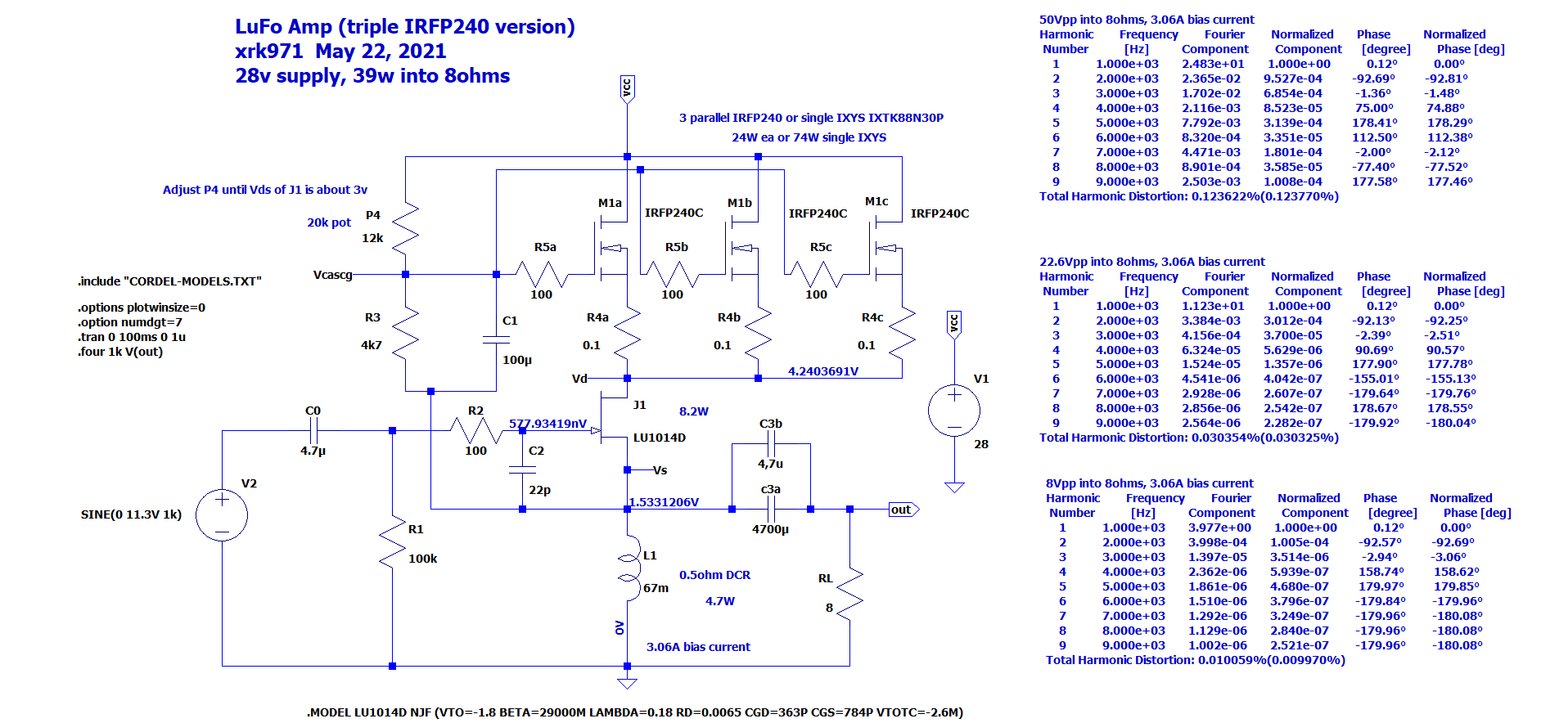
Vds across LU1014 should be around 2.7v.
Please measure all 3 pins and report back. Also measure all 3 pins at MOSFET and report here.
The LTSpice schematic shows nominal voltages.
Please measure all 3 pins and report back. Also measure all 3 pins at MOSFET and report here.
The LTSpice schematic shows nominal voltages.
Try loading the speaker output with a 100R, 2W resistor.DC offset : 1.78V
some wrong.
Then check DC offset again.

Good point, Vunce. On a cap output coupled amp, if there is no load or something to drain the charge buildup to ground, it will acquire a voltage offset.
@xrk971 @Vunce
Thank you!
I measured again with 8ohms 50W resistor.
DC offset below 0.1mV.
Vds of LU : 2.27V
P102 - P108 : 0.098V
P104 - P108 : 0.110V
P106 - P108 : 0.144V
... and I adjusted Vds to about 2.6V with R184 trimpot.
Vds of LU : 2.70V
P102 - P108 : 0.063V
P104 - P108 : 0.093V
P106 - P108 : 0.120V
I'm using two heatskinks with no heat spreading part. 55 C of one heatsink and 25 C of other heatsink.
Then now, what I could the other tasks ... adjusting bias or measuring other points?
Last edited:
If LU Vs is about 1.5v and inductor DCR is 0.5ohm then bias current is 3A. Can also be confirmed by measuring voltage across source resistors above LU. 55C temp on heatsinks appears to indicate you have proper current. It should play music.
Ohms law apply to each to calculate current then add all three since in parallel. Assuming the three big white resistors are 0.22ohms:
P102 - P108 : 0.10V —> I=0.1v/0.22ohm=0.45A
P104 - P108 : 0.11V —> I=0.11v/0.22ohm=0.5A
P106 - P108 : 0.09V —> I=0.09v/0.22ohm=0.41A
0.45+0.50+0.41A = 1.36A
But if you have 0.1ohm resistors then current is about 3A. Or if your inductor DCR is 1ohm vs nominal 0.5ohm per design then currrent is 1.5A.
What is DCR of the CH4 signal transformer used for inductor?


Looks like you are measuring across correct test points.
Or measure voltage across the two white BPR resistors on SLB. I think these are 0.1ohm+0.1ohm = 0.2ohms.
P102 - P108 : 0.10V —> I=0.1v/0.22ohm=0.45A
P104 - P108 : 0.11V —> I=0.11v/0.22ohm=0.5A
P106 - P108 : 0.09V —> I=0.09v/0.22ohm=0.41A
0.45+0.50+0.41A = 1.36A
But if you have 0.1ohm resistors then current is about 3A. Or if your inductor DCR is 1ohm vs nominal 0.5ohm per design then currrent is 1.5A.
What is DCR of the CH4 signal transformer used for inductor?
Looks like you are measuring across correct test points.
Or measure voltage across the two white BPR resistors on SLB. I think these are 0.1ohm+0.1ohm = 0.2ohms.
Last edited:
What is purpose of testing points P121, P122?
P121 - P122 : 1.6V at powering up -> 1.8V in 20 minutes
DCR of CH-4 is 0.6ohms in its' spec.
1.8V / 0.6ohm = 3A <- Is this bias current?
P121 - P122 : 1.6V at powering up -> 1.8V in 20 minutes
DCR of CH-4 is 0.6ohms in its' spec.
1.8V / 0.6ohm = 3A <- Is this bias current?
- Home
- Amplifiers
- Pass Labs
- LuFo Amp - 39w SE Class A from 28v Rail