No, but here are the files. The rev 3 schematic is just updated values.
It has a few modifications but can be used for the original circuit as well.
It looks like you posted the schematic to your ccfb board but the board you posted is your SIT DEF.
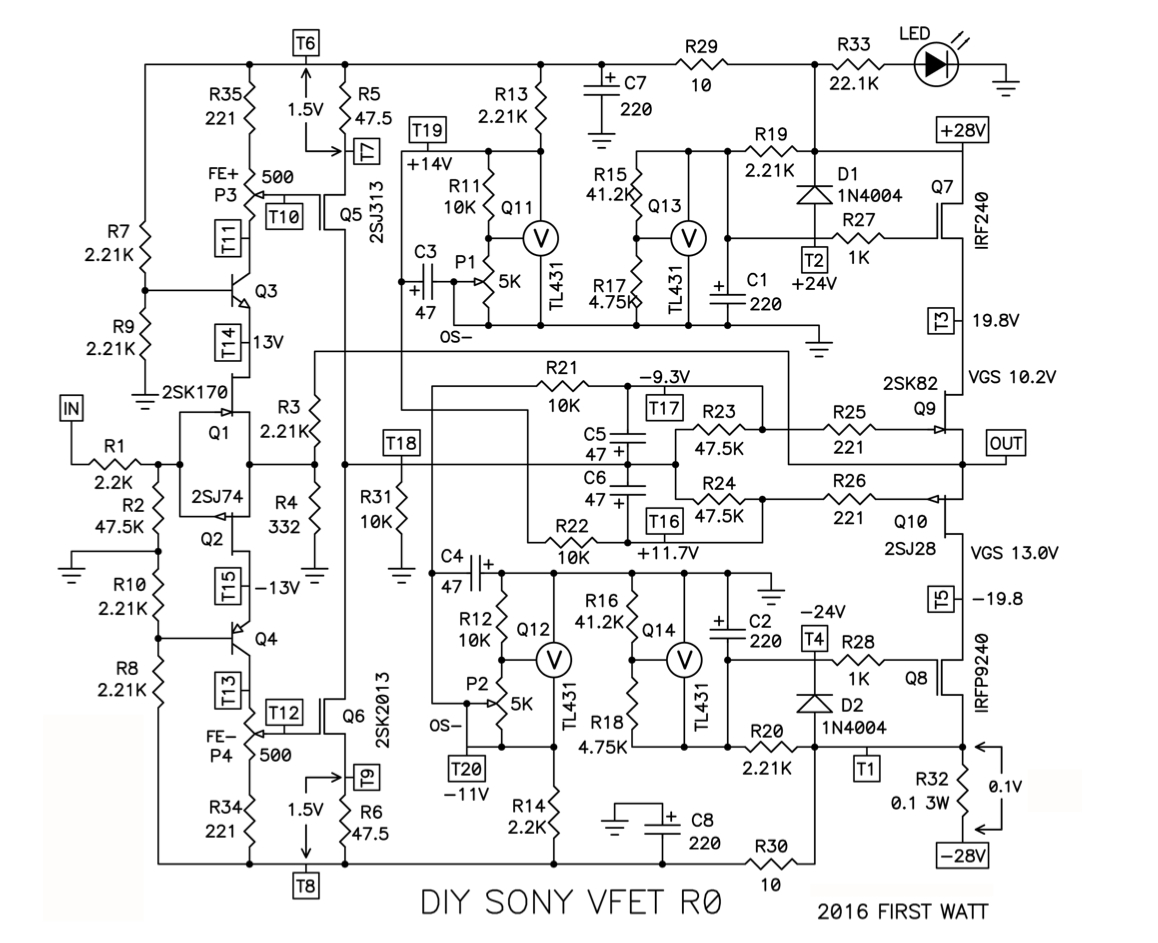
I think it’s called CCFB but is the same circuit that is was shown as a half snippet of the FE for the Sony VFET:
Last edited:
'I am not so sure if unobtanium Toshiba 2SK2013 and 2SJ313’s are really needed nowadays'
FQP3N30 & FQP3P20 are a nice alternative, pin out is the same.
FQP3N30 & FQP3P20 are a nice alternative, pin out is the same.
Hi Itsmee,
Thanks for that recommendation. I have used Fairchild FQP TO220’s before and really like how they sound.
Thanks for that recommendation. I have used Fairchild FQP TO220’s before and really like how they sound.
It looks like you posted the schematic to your ccfb board but the board you posted is your SIT DEF.
It’s the original CasCode FeedBack version from the dual output Vfet part 2. Without the tl431 regulators, and a big cap in there place.
Just don’t install the cascode feedback resistors. It also has the large caps to bypass the source resistor on the outputs.
Oh and I see I put up the wrong boards.
I will add the correct Gerbers
Last edited:
Here are the correct files.
Thanks. Very nice work on both boards. Can you post your schematic for the DEF board shared? It is more than worthy of a build.
It’s not a DEF, it’s just a big version of the new Vfet follower. I just flipped it for a negative supply and run it at -65v. Sounds great. I’m waiting for Nelsons version to see how it compares.
See Single Ended Tokin SIT THF-51S Common Drain Mu Follower Amplifier , 45W?
See Single Ended Tokin SIT THF-51S Common Drain Mu Follower Amplifier , 45W?
Last edited:
It’s not a DEF, it’s just a big version of the new Vfet follower. I just flipped it for a negative supply and run it at -65v. Sounds great. I’m waiting for Nelsons version to see how it compares.
See Single Ended Tokin SIT THF-51S Common Drain Mu Follower Amplifier , 45W?
I see it now. Thanks.
I built that 5 years ago and used dead IRFP240's as heatsink clamps for the LU's because they were so tricky to mount. It was a DC coupled headphone amp that probably had more power than I needed. Also 0dB gain and I made a cute little hand etched BF862 front end using Juma's design. I can't believe it has been 5 years since I set the LU1014D aside due to its tricky to mount requirements - which is no longer an issue.

Last edited:
No, but here are the files. The rev 3 schematic is just updated values.
It has a few modifications but can be used for the original circuit as well.
Can it drive LuFo to 39w with the rails of +-25v?
Abd what is the power neds (mA)?
You will need power supply to be a bit higher than 50v in order to drive 50Vpp (unless bootstrapped outputs are employed). 39w rms into 8ohms is 50Vpp. With MOSFET outputs, there is probably about 3v drop per leg so need at least 56v or +/-28v rails. Then there is the question of distortion when driven at such high amplitudes - it has to be modeled, optimized and verified for 50Vpp operation. This be a one reason I wanted to try a HV opamp designed to swing as high as 100Vpp. The 50Vpp would be well within its operating range.
But it is a welcome addition to be able to have another high swinging discrete FE.
But it is a welcome addition to be able to have another high swinging discrete FE.
Last edited:
Can someone please look into the possibility to run ACP+ at 55v rail with reduced bias current?
A scaled up F4, MoFo, LuFo friendly ACP+ would be awesome if it could retain the same character and be done with minimal changes. I'm more technician than I am engineer so hopefully someone smarter than me comes up with something.
- Home
- Amplifiers
- Pass Labs
- LuFo Amp - 39w SE Class A from 28v Rail