I like the idea of winding a custom choke onto a better core. I would probably target an inductance of 70 mH with a DC resistance of about 0.50 to 0.60 Ohm.
I think it would be easier to ship used 120V MOTs from the states or china to Europe
but where to find a supplier?
but where to find a supplier?
The DCR of 240vac MOTs is in the 2-3ohms and wire is skinny. It would require 4 in parallel - now the cost advantage is lost. Plus 24lbs of chokes per channel is heavy.
Last edited:
X, Daanve, others,
Throwing this out there, how about this:
https://www.lundahltransformers.com/wp-content/uploads/datasheets/2773.pdf
With both coils in series configuration and 3.5A rating?
Best,
Anand.
Throwing this out there, how about this:
https://www.lundahltransformers.com/wp-content/uploads/datasheets/2773.pdf
With both coils in series configuration and 3.5A rating?
Best,
Anand.
I think I'll go for 195T5 or custom FIAT inductors. And a modified Marantz7 for the big voltage gain...
A dumb (Or maybe not)question, would it be possible to use a tube for the the voltage gain. maybe 6C45 or 6SL7 or maybe a 2step with 6SN7?
A dumb (Or maybe not)question, would it be possible to use a tube for the the voltage gain. maybe 6C45 or 6SL7 or maybe a 2step with 6SN7?
Of course you can! Just need a tube preamp that can drive 50Vpp into 10k cleanly.
Maybe simple two stages 6sl7 with cathode follower on output would be ok.
Wow, X, they're very nice!!! Waiting for GB or Etsy selling 🙂
Wow, X, they're very nice!!! Waiting for GB or Etsy selling 🙂
Does anyone know if the Marantz 7 tube pre can drive 50Vpp out?
A quick search turned up some clones pre-built:
Finished Marantz 7 m7 Tube Pre-amplifier 6z5p+12ax7b Tubes Amp | eBay
We need to verify that it works first and correct any errors before they are released. Thanks for your patience.
A quick search turned up some clones pre-built:
Finished Marantz 7 m7 Tube Pre-amplifier 6z5p+12ax7b Tubes Amp | eBay
Waiting for GB or Etsy selling
We need to verify that it works first and correct any errors before they are released. Thanks for your patience.
Last edited:

Marantz 7 should be able to drive 50Vpp, but it is not the best option IMO and E to drive the gate of a power fet.
12AX7 tubes run on low current, despite the fact that it has a CF output; I saw a schematic with two 12AX7 in series with feedback to get the voltage amplification down to workable values, followed by 12AX7 cathode follower...arghhh...my tube heart hurts...
A much better option will be an Aikido preamp/driver stage.
A 6N1P as input tube and a potent tube as cathode follower (5687; 6H6P; ECC99) would give a stage with a bit over 1 VRMS sensitivity to drive a LuFo.
Broskie has high quality PCB's and multiple options as well for power supply.
A Broskie CCDA might work equally well, however, as LuFo is a quiet amp an Aikido might be a better fit.
Just thinking out loud.But is a 6C45 able to do this (by it self),it has a mu of 52 and can drive some current.
Edit: And use a CCS.
Edit: And use a CCS.
Last edited:
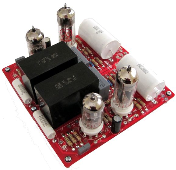
Here is a Broskie Aikido Noval:
New topic - LuFo as headphone amp:
I ran some simulations with 24v supply and a 20mH 0.5ohm inductor. The results were very promising as a headphone amp driving a 32ohm load. I might have to give this a try - will need to order these iron core speaker inductors.

ERSE Super Q 20mH 16 AWG 500W Inductor Crossover Coil
I was getting nothing but second harmonic distortion at 500mW into 32ohms (a little under 12vpp) and 0.0007% THD.
New topic - LuFo as headphone amp:
I ran some simulations with 24v supply and a 20mH 0.5ohm inductor. The results were very promising as a headphone amp driving a 32ohm load. I might have to give this a try - will need to order these iron core speaker inductors.
ERSE Super Q 20mH 16 AWG 500W Inductor Crossover Coil
I was getting nothing but second harmonic distortion at 500mW into 32ohms (a little under 12vpp) and 0.0007% THD.
Last edited:
With mere simulation don't you take possible core saturation out of the equation?
I'd like to see some real measurements with MOT's running in a 3A DC bias LuFo driving an 8 ohm load at 20 Hz full power.
That would give real info on the requirements for these chokes.
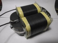
In the meantime I also had a prototype choke wound on a 300 watt c-core.
It has some 0.4 ohm DCR and 50 mH induction; this induction is measured with a (professional) induction meter at 100 Hz and 250 mV sinus.
It has quite an airgap, but behaviour must be checked in a working amp; I would not be surprised if a 600 watt core is required in the end.
I'd like to see some real measurements with MOT's running in a 3A DC bias LuFo driving an 8 ohm load at 20 Hz full power.
That would give real info on the requirements for these chokes.
In the meantime I also had a prototype choke wound on a 300 watt c-core.
It has some 0.4 ohm DCR and 50 mH induction; this induction is measured with a (professional) induction meter at 100 Hz and 250 mV sinus.
It has quite an airgap, but behaviour must be checked in a working amp; I would not be surprised if a 600 watt core is required in the end.
Attachments
With mere simulation don't you take possible core saturation out of the equation?
I'd like to see some real measurements with MOT's running in a 3A DC bias LuFo driving an 8 ohm load at 20 Hz full power.
That would give real info on the requirements for these chokes.
In the meantime I also had a prototype choke wound on a 300 watt c-core.
It has some 0.4 ohm DCR and 50 mH induction; this induction is measured with a (professional) induction meter at 100 Hz and 250 mV sinus.
It has quite an airgap, but behaviour must be checked in a working amp; I would not be surprised if a 600 watt core is required in the end.
That is a nice looking choke.
- Home
- Amplifiers
- Pass Labs
- LuFo Amp - 39w SE Class A from 28v Rail