I guess we have to see what the Vpp is at 20Hz vs 1kHz into an 8ohm dummy load. Although that’s HT bass, I think the majority of bass we need for dynamics is kick drum which is centered around 50Hz. 20Hz is artificial flappy bass. Unless you listen to cathedral organs, very few instruments make music down below 40Hz.
Last edited:
My gain stage was a discrete SE Class A affair using 55v single rail. I don’t think you need 100vpp.
Take a look at OPA454. $6 part with nice specs (+/-50v) and give it say +/-35v should do the trick.
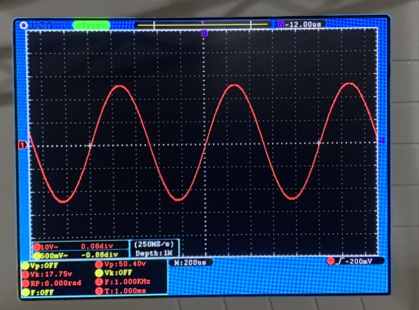
Sorry, I screwed the math. 17.7V RMS is 25Vp or 50Vpp.
That should be easy.
Best,
Anand.
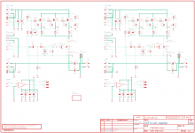
Here is the latest LuFo amp schematic that corresponds to the prototype PCBs that have been placed. I have added an (optional) TVS protection diode across the JFET drain-source to protect from any transient above 18v (clamping voltage). The boards are made in mirror symmetry for Left/Right channels. JPS64 tells me that there are 21,000 via drill holes to stitch the two sides together!

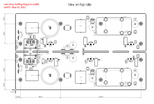
Stuffing Diagram:

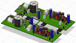
3D render of both boards (panel size is 260mm x 152mm):

The BOM is in a zipped Excel file below.
Stuffing Diagram:
3D render of both boards (panel size is 260mm x 152mm):
The BOM is in a zipped Excel file below.
Attachments
-
LUFO-AMP_Proto_SCH_27_05_2021.pdf124.6 KB · Views: 188
-
 Lufo-Schematic-Prototype-v001-May-27-2021.png335.8 KB · Views: 1,294
 -
 Lufo-Stuffing-Diag-Prototype-v001-May-27-2021.png206.9 KB · Views: 1,506
 -
 LUFO_View3-render.jpg254.3 KB · Views: 1,385
 -
Lufo-BOM-Prototype-v001-May-27-2021..zip27.1 KB · Views: 168
Last edited:

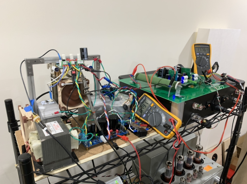
I ran the LuFo with the new LD1014D at 39.5w for a full 30min. No problems and works like a champ. Here is new setup on my front of the house amp rack so that I can listen to the LuFo on my main 10F/RS225 TL speakers. The stress test was on the 100w wire wound dummy load resistor (green cylinder on top of the large green PCB). I even took it to 6A bias current for a few minutes to explore possibility of driving 4ohm loads. With a fan on the LD1014D heatsink it was no problem.
Ok, I bit the bullet and ordered a set of LD1014D JFets, plus added my name to the LD1014 PCB spreadsheet. More stuff to build.
I am curious about the three IRFP240 Mosfets. There seem to be other possibilities, such as two IRFP150, two FQH44N10, or even a single IRFP250. Have any of these been tried yet?
I am curious about the three IRFP240 Mosfets. There seem to be other possibilities, such as two IRFP150, two FQH44N10, or even a single IRFP250. Have any of these been tried yet?
Hi Tungsten Audio (have you ever gone by Wolfram? 🙂)
Cool that you got the devices. Although at $0.17ea, not much of a bullet to bite. That’s less than a typical TO-92 BJT like KSC1845 from Mouser.
Almost any N channel HEXFET can work here. I am actually using some old Phillips “TrenchFETs”. They are cascodes and so being there to reduce the voltage the JFET sees but the musicality is coming from the JFET as all the current passes through it and is modulated by the JFET. I would normally use one big IXYS and a CPU cooler. For the demo I used more conventional lower wattage (I stuck all three on the same CPU cooler). If you go with a single device, the heat flux is higher and a passive heatsink may not be adequate for 75w from a TO-247/TO-3P.
The reason three MOSFETs were used was to spread the load across a larger passive heatsink, a preferred method to reduce the thermal load with amps folks like to build on this forum.
Last edited:
Very nice work, X. I would suspect that 6A bias would sound some better than 3A bias and measure some better. Mr. Pass has commented that the more you make the devices work, the better they sound. The LU should not be leaving the triode region even at 15A peaks. Lots of triode region headroom.
Fantastic work here Fellas! Love the mirror image pcb layout.
Looking forward to building LuFo 😉
Thanks JPS64 and X!!
Looking forward to building LuFo 😉
Thanks JPS64 and X!!
Very nice work, X. I would suspect that 6A bias would sound some better than 3A bias and measure some better. Mr. Pass has commented that the more you make the devices work, the better they sound. The LU should not be leaving the triode region even at 15A peaks. Lots of triode region headroom.
Well, I have CPU coolers and fan to extract 150w from the 3 MOSFETs and 20W front the JFET. I can employ the currently unused secondary from the power trafo and connect it in parallel to extract more current. Crank up to 6A and see what it sounds like. It already sounds gloriously powerful and smooth. Could it get better? Sure. 😀
Looks like this is going to be a 400VA 25v Antek per channel amp then. Good thing I already have a pair.
Given that each channel has a 400VA donut plus a 10lb MOT, I think a monoblock chassis is the way to go to save one’s back when moving them.
Last edited:
X. Looks like a great amp. Between it and the AN, presuming sound quality is comparable, which puts out less heat / is easier to build?
So does the choke run off the single rail supplied voltage like in the MoFo? Just trying to figure out the best way to power this amp including the yarra cards, based on what I have available.
I think the AN and LuFo are about a wash (even) in terms of thermal output. One has double the rails but half the bias current. The other has half the voltage, but twice the bias current. 🙂
The LuFo is certainly easier to build assuming you have a preamp capable of driving 50Vpp. If you have to also build a preamp then I would say the AN is easier to build. Although, I am investigating a simple OPA454 opamp daughter board front end that can drive the LuFo into full output from a +/-35v DCDC supply.
Yes, single rail PSU running at 3A or more is needed.
The LuFo is certainly easier to build assuming you have a preamp capable of driving 50Vpp. If you have to also build a preamp then I would say the AN is easier to build. Although, I am investigating a simple OPA454 opamp daughter board front end that can drive the LuFo into full output from a +/-35v DCDC supply.
So does the choke run off the single rail supplied voltage like in the MoFo?
Yes, single rail PSU running at 3A or more is needed.
Last edited:
OPA552 is also a good choice but requires lower rails, say +/-28v to make sure we stay within max rated voltage. It’s got 200mA output - which I don’t think we need because the OPA454 has 50mA which should be more than enough. Either can work though.
I just ordered a pair of each OPA454 and OPA552 to play with and see if this works. What would be cool is a M2X/Yarra format universal vero board PCB for experimenting. 🙂
Although I think an ACP+ M2X format board could be adapted for this purpose.
I just ordered a pair of each OPA454 and OPA552 to play with and see if this works. What would be cool is a M2X/Yarra format universal vero board PCB for experimenting. 🙂
Although I think an ACP+ M2X format board could be adapted for this purpose.
Last edited:
>Although I think an ACP+ M2X format board could be adapted for this purpose.
This probably will be my way to go 🙂
This probably will be my way to go 🙂
Well, I am playing the amp at 6.0A bias current and maintaining 28.1vdc at the amp supply now with both secondaries of the the 400VA trafo being employed. (This says that if running 3A bias current, a single 400VA trafo should be enough for a dual mono stereo setup). I decreased the resistance and increased the power dissipation of the CRC resistor by using 4x 0.33ohm 3W Vishay in parallel. With two in parallel the resistor was hitting 190C, now running at 104C. Music sounds good! Temp of LD1014D body is 54C and air blowing out of CPU cooler for the three MOSFETs is 50C - fan speed kicked up a notch with the auto temp feedback speed of the PWM controller doing its thung.'
The amp is still absolutely silent with no music playing. Quiet as in you cannot tell it is turned on with ear pressed to speaker cone. The DIY Sony VFET amp is also like this but uses a SMPS whereas here this is a linear supply.
Video from my phone of test track:
LuFo amp running at 6.0A bias current and 28.1v. Driving 10F/RS225 TL speakers. - YouTube
Last edited:
- Home
- Amplifiers
- Pass Labs
- LuFo Amp - 39w SE Class A from 28v Rail