Great option
Very creative.
I was thinking of disposing my surplus, but with this, might wait a little longer.
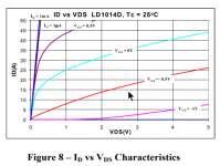
Do you need matched pair of LU104's for the design?
Very creative.
I was thinking of disposing my surplus, but with this, might wait a little longer.
Do you need matched pair of LU104's for the design?
.......
Do you need matched pair of LU104's for the design?
Ideally, yes
Non ideally - I believe some tweedldee with trimpot for LU's Uds ( +/-100mV) should equalize things, but necessary usage of THD Spectra measuring setup
In case of matched pair being on disposal, mentioned tweedledee possible using just ears for judging - change both up/down to same value , listen , make notes, change again, listen, make notes - choose what value ticks most boxes
Though, I believe with some luck , LU1014 are not so hard to find
There was US based surplus parts selling company, of which I can't recall a name, selling real deal ....... I'll try some googlll these days, hoping to stumble on that source........ if some good soul doesn't chime in with remembered info
If ( that most likely) and when I have everything in numbers, I'll be able to dispatch LU's for at least 35 stereo kits
... I can't keep up yet nonetheless feel the urge to build one... 😀
The Greedy Boy Mantra
Keeping up with Zen’s amp design ideas is like trying to count cards like Rainman.
Fugly!!!
I don't want it 😡
changed my mind ... who am I trying to kid 😉😀
I just want to read more newspapers from Choky-land, not that interested in building amps 🙄
I don't want it 😡
changed my mind ... who am I trying to kid 😉😀
I just want to read more newspapers from Choky-land, not that interested in building amps 🙄
The spektrum plots shown in posts# 3-5 are perfect.
But I fear the worst that ZM will admit to greedy boyz his early April Fools Day hoax soon and these plots are photoshopped. 😀
Well done.
But I fear the worst that ZM will admit to greedy boyz his early April Fools Day hoax soon and these plots are photoshopped. 😀
Well done.
The spektrum plots shown in posts# 3-5 are perfect.
.......
and, again, even I must remind my self that there is no Loop NFB , at all!?!
........
But I fear the worst that ZM will admit to greedy boyz his early April Fools Day hoax soon and these plots are photoshopped. 😀
.......
Ha! How it didn't came to me .........

Though - perfectly nice idea, and April 1. is near

can you explain a bit the bias system especially the role of ic101?
I really like the idea of measuring current at a drain resistor avoiding source degeneration
I really like the idea of measuring current at a drain resistor avoiding source degeneration
will knock few sketches this evening
at gates side, pretty much the same as in M2 ( Best Papamp ever)
difference is at feeding side of optocouplers
at gates side, pretty much the same as in M2 ( Best Papamp ever)
difference is at feeding side of optocouplers
Yes input a la M2 with your iron pumpkin buffer
Bias seems a bit complex with so many zeners current source and opto... For sure a smart way to avoid hall current sensors...
Bias seems a bit complex with so many zeners current source and opto... For sure a smart way to avoid hall current sensors...
little earlier than this evening
well, really nothing new under the Sun - meaning there is hardly anything specially new or unique that I put here
even if Papa really started us Greedy Boyz playing with Square Law OS arrangements, thing is old as Wheel, in fact
also - using rail series resistors, again Papa's bag of tricks ( for us) but again nothing especially new
neither source follower ( which is introduced here in front of upper output device) used as level shifter is anything new .....
thing is - it's hard to make anything absolutely unique, and wishing just that is right recipe to get yourself in not making anything at all ....... so , studying schematics from everywhere and one can just hope to get in situation to stand on Giant's shoulders
one day ...... one day ............ 🙂
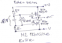
anyway - here is basic , lets call it , M2 biasing mechanismus;
simple as that:
we have R+ connected to upper part gate,
we have R- connected to lower part gate,
we have some variable impedance connected between gates; varying that impedance we are varying voltage sag across R+ and R- , thus positioning gates at appropriate voltage potential ( one vs. another) , thus setting how much Iq will pass trough output devices
call that variable impedance Rvar, further Mech. , shorted of mechanismus 🙂
cap between gates is there to eliminate AC to appear between gates - we don't want that ........ and also worth to mention - R+ and R- are sorta same in value , difference being just what we need to set output offset to 0 ( N gate and P gate voltages not exactly being identical)
can you explain a bit the bias system especially the role of ic101?
I really like the idea of measuring current at a drain resistor avoiding source degeneration
Yes input a la M2 with your iron pumpkin buffer
Bias seems a bit complex with so many zeners current source and opto... For sure a smart way to avoid hall current sensors...
well, really nothing new under the Sun - meaning there is hardly anything specially new or unique that I put here
even if Papa really started us Greedy Boyz playing with Square Law OS arrangements, thing is old as Wheel, in fact
also - using rail series resistors, again Papa's bag of tricks ( for us) but again nothing especially new
neither source follower ( which is introduced here in front of upper output device) used as level shifter is anything new .....
thing is - it's hard to make anything absolutely unique, and wishing just that is right recipe to get yourself in not making anything at all ....... so , studying schematics from everywhere and one can just hope to get in situation to stand on Giant's shoulders
one day ...... one day ............ 🙂
anyway - here is basic , lets call it , M2 biasing mechanismus;
simple as that:
we have R+ connected to upper part gate,
we have R- connected to lower part gate,
we have some variable impedance connected between gates; varying that impedance we are varying voltage sag across R+ and R- , thus positioning gates at appropriate voltage potential ( one vs. another) , thus setting how much Iq will pass trough output devices
call that variable impedance Rvar, further Mech. , shorted of mechanismus 🙂
cap between gates is there to eliminate AC to appear between gates - we don't want that ........ and also worth to mention - R+ and R- are sorta same in value , difference being just what we need to set output offset to 0 ( N gate and P gate voltages not exactly being identical)
Attachments
M2 in more details;
as said - it's relatively easy when we want to use source resistors as Iq reference points; I mean - easy when we got recipe from Mithrandir
also easy when we are using lower and upper output parts having so-so equal gate voltages, opposite side of output node, meaning +4V and -4V
optodiode connected across source resistors, series resistor to optodiode taking care that diode is not getting more than nominally 1V1 , at preferred Iq through source resistors
opto transisttor is now MECH. , governing current through R+ and R- , everything is Wine and Roses
Attachments

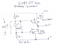
now - Bummer
things are getting tricky when we want to use different part than Mosfet ( either up or down) , while using same biasing technique
say SissySIT (DEFiSIT) - Toking Bigun is different to N mosfet in that way that gate voltage is opposite in sign (differene between enhanced vs. depletion mode parts, +4V-ish vs. -3V-ish)
now voltage window between gates is no more twice 4v (+4V reaching down to -4V), now it is -3Vsomething reaching to -4V
we are happy campers if we have SIT with Ugs no greater in number than, say , 3V7 , so we have big enaough voltage window between gates, to squeeze optotransistor in
some P mosfets are having Ugs in range of -4V5, thus allowing as little broader batch of Tokins to be used, but that's just one more thing to take care with, endless parts picking .......
current through R+ and R- is, logically, one current; due to fact that gates are not symmetrical to output node, now R+ and R- can't be approx. same in value, resulting in few problems, of which most important one is that mains fluctuation resulting in sliding output DC offset , also parts TempCo playing game with Iq, then rails fluctuating down ( if not regged) etc.
Luckily , I succeeded more or less in set of compromises while making SissySIT , both first one and R.2
Attachments
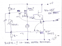
now, how to solve those issues ...... unequal Rail resistors , SIT parts with greater Ugs number ..... sometimes time is needed either to make space for new problems in thick skull, or just to have some leeway, then be able to step aside and look at problem from another point
level shifter part, that's it
small mosfet, so Ugs is sorta symmetric to big mosfet down Ugs, .... suddenly Rail resistors are sorta equal again, practically no gate currents to complicate things ( as is case with some not so well behaving Tokins)
principal schm down; ignore MECH. principle fro now
I think everything is clear, except note about LS resistor - its value is roughly SIT Ugs divided with current trough small Mosf/LS res./CCS ;say that you put value just being in ballpark; you can always go back and alter its value , to get wanted symmetry of lower and upper mosfet Ugs values
Attachments
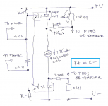
now, as all important is explained, time to mull about rail sense
I know for sure that Pa is using something in that manner already in PL products, but him being Pa - solving everything with resistors and zeners as level shifters
Mighty ZM , being chicken , I didn't up to recently even know that resistor can be described as CCS ( even if poor one), and I decided to use helper CCS ( see explanation) in form of ultramumbojumbo5$specialpart
in M2 case - wee see that optodiode is fed with voltage from source resistors, where we have voltage in abundance, even shaving it with series resistor
in SissySIT ( still damn good piece of work, if you ask Mighty Modesty Moi), I did use Hall chips ( tnx, Mighty Indra) ....... slope of voltage given at chip output is (2V5 to 5V)/(0 to 5A) ........ but effectively lower due to all summing and whatnot; didn't tried zeners as level shifters to decrease summing losses, but damn slope must be same , shifted with resistors or with anything else
working, but I maybe didn't knew that I can do better, but I obviously wished that I can do better, regarding Iq and offset stability in rail voltage/temp/time domains
so, if one choose to use ( minimal needed value of) rail resistors as current sense chain, even with 0R11 ( two of 0R22 in parallel) we have better effective voltage slope with current change ; numbers doesn't compute exactly, but from actual circuit, behavior is better than with Hall Chips
now ....... say that current is 1A5 , as in LuDEF
we have 165mV across 0R11 sense resistor......... ( I didn't want bigger value, sue me ...... later I got that voltage slope is enough with that value ) ..... but optoled needs nominally 1V1 to shine happily ............. so- there is a trick with helper CCS ( again, Pa using resistor there) , which is going to add some voltage to optoled - simple addition of 220R resistor and CCS pulling some current , we got additional 935mV
from there, when you gotta that optoled is shining happy, everything is just matter of more or less voltage through series 0R11
all that nicely transposed to opto in lower rail, so we now have rail resistors, each of them having own optotransistor to pull current trough, optotransistors are summed together
again, cap between two rail resistors, if using any of preceeding solutions with two mosfet gates ( one up, one down) we have symmetrical values of rail resistors, everything behaving nicely and polite and .......... almost boring
(M2 is same boring, regarding that)
so, what was left - put all these puzzle pieces on table and combine them
much greater problem is to choose which one of wast number of permutations is worthy of becoming an amp, than drawing any of them
if I forgot something , blame Pa
I know for sure that Pa is using something in that manner already in PL products, but him being Pa - solving everything with resistors and zeners as level shifters
Mighty ZM , being chicken , I didn't up to recently even know that resistor can be described as CCS ( even if poor one), and I decided to use helper CCS ( see explanation) in form of ultramumbojumbo5$specialpart
in M2 case - wee see that optodiode is fed with voltage from source resistors, where we have voltage in abundance, even shaving it with series resistor
in SissySIT ( still damn good piece of work, if you ask Mighty Modesty Moi), I did use Hall chips ( tnx, Mighty Indra) ....... slope of voltage given at chip output is (2V5 to 5V)/(0 to 5A) ........ but effectively lower due to all summing and whatnot; didn't tried zeners as level shifters to decrease summing losses, but damn slope must be same , shifted with resistors or with anything else
working, but I maybe didn't knew that I can do better, but I obviously wished that I can do better, regarding Iq and offset stability in rail voltage/temp/time domains
so, if one choose to use ( minimal needed value of) rail resistors as current sense chain, even with 0R11 ( two of 0R22 in parallel) we have better effective voltage slope with current change ; numbers doesn't compute exactly, but from actual circuit, behavior is better than with Hall Chips
now ....... say that current is 1A5 , as in LuDEF
we have 165mV across 0R11 sense resistor......... ( I didn't want bigger value, sue me
...... later I got that voltage slope is enough with that value ) ..... but optoled needs nominally 1V1 to shine happily ............. so- there is a trick with helper CCS ( again, Pa using resistor there) , which is going to add some voltage to optoled - simple addition of 220R resistor and CCS pulling some current , we got additional 935mVfrom there, when you gotta that optoled is shining happy, everything is just matter of more or less voltage through series 0R11
all that nicely transposed to opto in lower rail, so we now have rail resistors, each of them having own optotransistor to pull current trough, optotransistors are summed together
again, cap between two rail resistors, if using any of preceeding solutions with two mosfet gates ( one up, one down) we have symmetrical values of rail resistors, everything behaving nicely and polite and .......... almost boring
(M2 is same boring, regarding that)
so, what was left - put all these puzzle pieces on table and combine them
much greater problem is to choose which one of wast number of permutations is worthy of becoming an amp, than drawing any of them
if I forgot something , blame Pa
Attachments
Last edited:
everything is matter of compromises
I know what I got this way .... with resistor in same place, behavior set would be different - increasing Iq with rails sag etc.
so, as with many other things, choose your own poison and go with it
5 greenies part per channel is not too big inconvenience, if I'm better sleeping
I know what I got this way .... with resistor in same place, behavior set would be different - increasing Iq with rails sag etc.
so, as with many other things, choose your own poison and go with it
5 greenies part per channel is not too big inconvenience, if I'm better sleeping
Yes input a la M2 with your iron pumpkin buffer
Bias seems a bit complex with so many zeners current source and opto... For sure a smart way to avoid hall current sensors...
zeners in LuDEF - "just" protecting parts - regular over the rail modulation etc.
had clamping 1N4148 diodes on both sides for that, in prototype, decided to leave them out and put that to zeners
3 at gates
zeners in series with CCS - voltage umbrella (max 40Vdc for part) , 120R ditto to CCS are antioscillation measurements
- Home
- Amplifiers
- Pass Labs
- LuDEF