The recommended version is now https://www.diyaudio.com/community/...-watt-with-low-distortion.397378/post-7306466
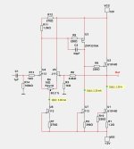
Power Supply in this post https://www.diyaudio.com/community/...-watt-with-low-distortion.397378/post-7311145
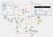
This amplifier uses two LU1014D JFET.
Max power output is like 6 Watt into 8 Ohm.
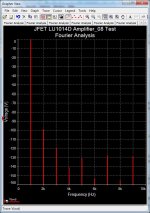
The distortion is low and mainly 2nd harmonic. As can be seen in image.
What you need:
4 x J113 JFET
1 x ZVP3310A MOSFET
2 x LU1014D Power JFET
And a good power supply 2x12VDC. Preferably regulated
The recommended version is now https://www.diyaudio.com/community/...-watt-with-low-distortion.397378/post-7306466
Power Supply in this post https://www.diyaudio.com/community/...-watt-with-low-distortion.397378/post-7311145
Power Supply in this post https://www.diyaudio.com/community/...-watt-with-low-distortion.397378/post-7311145
This amplifier uses two LU1014D JFET.
Max power output is like 6 Watt into 8 Ohm.
The distortion is low and mainly 2nd harmonic. As can be seen in image.
What you need:
4 x J113 JFET
1 x ZVP3310A MOSFET
2 x LU1014D Power JFET
And a good power supply 2x12VDC. Preferably regulated
The recommended version is now https://www.diyaudio.com/community/...-watt-with-low-distortion.397378/post-7306466
Power Supply in this post https://www.diyaudio.com/community/...-watt-with-low-distortion.397378/post-7311145
Attachments
Last edited:

The Fourier plot shows "Voltage (V)" on the y axis, ranging from 0 to -180. I don't think the max. really is zero Volts. Is there an error with the y axis somehow?
Nah. J113 is available from the big houses, and there are a bunch of group buys for the LU1014 (including mine, see my signature).Very nice, but those fets are impossible to get..
I have thousands of those. We could arrange some distribution or perhaps put them in the store.
Did I mention cheap?

Did I mention cheap?
I would say go for it , if you don't need that stash.
And yes you mentioned cheap.. great bait..👍
And yes you mentioned cheap.. great bait..👍
Would you be kind enough to match them in your Cascode circuit first and determine the optimum source resistor value before putting in the store ?
🤓
Patrick
🤓
Patrick
Last edited:
Gate bias can be adjusted in most cases, so Vgs matching is not that critical. However, the gain parameters (curve slopes) are all over the place wit the LUs. I would therefore recommend some sort of curve matching.
https://www.passdiy.com/gallery/amplifiers/zen-variations-9
Fig. 10
But of course not the same as curve tracing in triode cell.
https://www.diyaudio.com/community/threads/zen-variation-9.317131/post-5384547
Patrick
Fig. 10
But of course not the same as curve tracing in triode cell.
https://www.diyaudio.com/community/threads/zen-variation-9.317131/post-5384547
Patrick
@EUVL Your LU1014 curves look surprisingly similar. My experience with these parts is very different:
https://github.com/mbrennwa/curvetracedata/tree/main/LD1014
https://www.diyaudio.com/community/...-by-vgs-and-curve-tracing.381338/post-6902977
But let's go back to the nice little amp presented by the OP! @lineup did you measure the distortion spectrum, or is this a model calculation?
https://github.com/mbrennwa/curvetracedata/tree/main/LD1014
https://www.diyaudio.com/community/...-by-vgs-and-curve-tracing.381338/post-6902977
But let's go back to the nice little amp presented by the OP! @lineup did you measure the distortion spectrum, or is this a model calculation?
My experience with these parts is very differen
Sure.
For LU1014, I choose to define matching as <<1% over the entire operating range.
This allows me to cancel 30~40dB even harmonics in a balanced circuit.
My personal design choice.
Patrick
The distortion i SPICE is 0.00028% at 8 Ohm 1 Watt.@EUVL Your LU1014 curves look surprisingly similar. My experience with these parts is very different:
https://github.com/mbrennwa/curvetracedata/tree/main/LD1014
https://www.diyaudio.com/community/...-by-vgs-and-curve-tracing.381338/post-6902977
But let's go back to the nice little amp presented by the OP! @lineup did you measure the distortion spectrum, or is this a model calculation?
The Fourier spectrum then is like the image in my first post.
At 6 Watt the dist is like 0.020%
Of course I know that real life figures are not at all the same.
SPICE is a limited thing. Not for real.
Just gives you a hint what circuit may work.
I never actually build my circuits.
I leave that to others.
I am more of an idea maker. To inspire.
Nelson Pass is also an idea maker.
The difference is he actually make real amplifiers. And tests.
Last edited:
Sure you have Nelson.
My choice of transistors is depending on what goes on in this forum, Pass Labs.
My idea is that people will have them from Pass designs.
And so they can easily build my designs.
Sometimes it works. Sometimes my designs are forgotten - with no real use.
I do not like amplifiers with exotic devices. Such as ordinary people can not get them.
I think you know very well what I mean.
Your designs are exemplary in this respect.
🙂
Would using LSK170 or Toshiba K170 devices improve the distortion? I could get on board trying this design with the best devices. I have a large stash of LD1014D devices.
- Home
- Amplifiers
- Pass Labs
- LU1014D Small Amplifier 6 Watt with low distortion