This is probably most relevent to the New First Watt product at Axpona 2023 thread: https://www.diyaudio.com/community/threads/new-first-watt-product-at-axpona-2023.398259/post-7325220I think it would be case dependent. I guess I would consider 12 dB near the boundary.
I went back to the FrankenTracer data for 6 of my 2SK182ES SITs. Several years ago I put together some GNU Octave (pseudo Matlab) code to fit 2D polynomial surfaces Vgs(Vds,Id) to that data. From those surfaces it is easy to compute mu, gm, and Rd for a given operating point.
Here as a few examples:
SIT#1 Vds=30V Id=1.5A mu = 16.984 gm = 6.7570 Rd = 2.5135
SIT#2 Vds=30V Id=1.5A mu = 17.186 gm = 5.8923 Rd = 2.9166
SIT#3 Vds=30V Id=1.5A mu = 21.176 gm = 7.2821 Rd = 2.9080
SIT#4 Vds=30V Id=1.5A mu = 19.416 gm = 5.9390 Rd = 3.2691
SIT#5 Vds=30V Id=1.5A mu = 20.880 gm = 6.0735 Rd = 3.4379
SIT#6 Vds=30V Id=1.5A mu = 20.540 gm = 6.9906 Rd = 2.9383
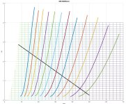
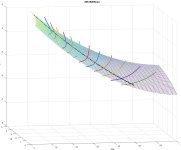
Below are images of the Vgs surface for SIT#4. The black line is a 16 Ohm load, corresponding to the load seen by the SIT when the mu follower and the SIT have equal, but opposite, AC currents.
Attachments

On those conditions no disclosure, nor for your father.
Prefer oblivion, and Pano knows. Count.
Prefer oblivion, and Pano knows. Count.