

It's kind of a small party, more like several of the boys sipping beers at the local car garage where they swap stories... 🙂
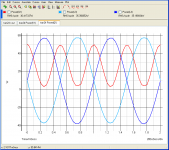
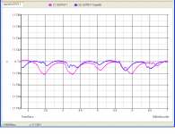
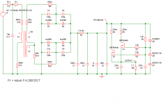
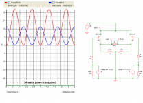
I'm developing a little power supply for my amp using Nelson's ideas with FET regulation. What I discovered, at least in the world of Sim, is that you can reverse phases on a center-tap transformer and cancel some of the unwanted noise in the power supply. Here's what I did:
Attachments
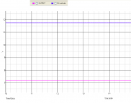
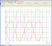
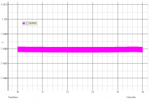
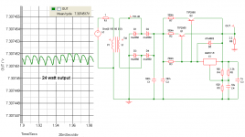
Oh, I forgot to mention: I'm going to build the little LU1014D jfet amp first. That's why the power supply is only 7.3 volts. Anyway, here's the last graph (with extreme magnification)--I'm rather astonished at what a few well placed resistors and capacitors can do.
Attachments
Hmm, we can't have you talking to yourself all the time 😉
So, have you actually built the amp?
Magura 🙂
So, have you actually built the amp?
Magura 🙂
Magura said:Hmm, we can't have you talking to yourself all the time 😉
So, have you actually built the amp?
Magura 🙂
Hahahahaaaaaa......... I do that a lot!
I'm in the process of gathering parts. I have most of them. 😀 It's fun playing with the sim, but the time has come to make my boy's lab pay for itself.
Happy holidays, Magura. Give the misses a hug from me as well--imagine having a mate sweet enough to play with your inductors on a cold winter evening.......chills.
I cobbled together two LU1014Ds (mounted on 2" x 4" x 1.5" heatsinks), four resistors, one transformer (choke), a 7.3 volt power supply: voila!
The damned thing works. Sounds good too!
I'm running it single-ended input until I can get a balanced lead hooked up.
Hahahahaaaaaaaaaaa.... 😎
The damned thing works. Sounds good too!
I'm running it single-ended input until I can get a balanced lead hooked up.
Hahahahaaaaaaaaaaa.... 😎
Hi Choky.
I'm going to fabricate the PS next, just have to get some of those big ol' PNP transistors.
I'm going to fabricate the PS next, just have to get some of those big ol' PNP transistors.
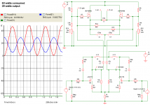
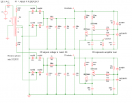
I've finished designing the power supply...
but in the meantime:
I had my sweet "golden ears" wife give my amp a listen. I tried different voltages and pointed to the LU1014D performance graph--as if one look would explain everything.
She looked at me as if I'd been couped up in my lab too long.
Her conclusion is as follows: Higher voltage/lower amperage = clear, brilliant high notes with a narrowness in ambiance. Lower voltage/proper amperage = warmer sound, smoother. Overall, warm and smooth gets the nod.
She does like the sound, but four volts leaves room for precious little output signal.
I could always explore, perhaps discover a way to lower the source resistance...
For the moment--tweaking is a favorite pastime--I discovered that the secondaries on my Plitrons are 0.1 ohm and have 30mH inductance. 30mH is a far cry from 225mH, but what the hell.

Why not give it a try.
Ok, bottom end is weaker--to be expected--but the mids and highs are so lush, and this is a 500hz to 20K amp for my sound system, yes?
I bravely bumped the variac dial upwards...
No smoke...phew.
I ended the adventure with 5.88 volts out of the power supply which gave me 4 volts across the Jfet's drain/source. I have 0.53 volts across the transformer (per leg). With 0.1 ohms resistance I figure I've got roughly 5.3 amps available per leg... times 4 volts drain/source gives me 21.2 watts through the Jfet. Forgive me, dear Nelson...
 until she blows.... I'll keep you guys posted. 😀
but in the meantime:
I had my sweet "golden ears" wife give my amp a listen. I tried different voltages and pointed to the LU1014D performance graph--as if one look would explain everything.
She looked at me as if I'd been couped up in my lab too long.
Her conclusion is as follows: Higher voltage/lower amperage = clear, brilliant high notes with a narrowness in ambiance. Lower voltage/proper amperage = warmer sound, smoother. Overall, warm and smooth gets the nod.
She does like the sound, but four volts leaves room for precious little output signal.
I could always explore, perhaps discover a way to lower the source resistance...
For the moment--tweaking is a favorite pastime--I discovered that the secondaries on my Plitrons are 0.1 ohm and have 30mH inductance. 30mH is a far cry from 225mH, but what the hell.
Why not give it a try.
Ok, bottom end is weaker--to be expected--but the mids and highs are so lush, and this is a 500hz to 20K amp for my sound system, yes?
I bravely bumped the variac dial upwards...
No smoke...phew.
I ended the adventure with 5.88 volts out of the power supply which gave me 4 volts across the Jfet's drain/source. I have 0.53 volts across the transformer (per leg). With 0.1 ohms resistance I figure I've got roughly 5.3 amps available per leg... times 4 volts drain/source gives me 21.2 watts through the Jfet. Forgive me, dear Nelson...
until she blows.... I'll keep you guys posted. 😀- Status
- Not open for further replies.
- Home
- Amplifiers
- Pass Labs
- LU1014 differential amplifier