carpenter said:
Gain dropped by half on source follower? Hahahah! 😀 😀 😀
Hi, Capenter,
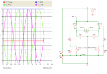
What about this . . . ? X-fied . . . ?
>>🙂<<
Attachments
I've got the sim out, so I'll try your idea and get back to you. 🙂
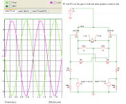
BTW, on the last schematic, I added a preamp to the circuit instead of using their wave source. I notice that it doesn't work unless I add a couple of caps in the feedback loops. I'm still playing, though...
BTW, on the last schematic, I added a preamp to the circuit instead of using their wave source. I notice that it doesn't work unless I add a couple of caps in the feedback loops. I'm still playing, though...
flg said:Can you do that
Don't want to be to positive
😉
I'm afraid you shot right over my head (your comment that is).😀
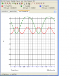
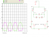
I figured out a way to increase jfet current--I think...
Sim says it went from 1.8 amps to 3.2 amps. There is a small voltage penalty. One could always increase overall voltage to accommodate the voltage shift.
I'm not certain if it's permissible to create a virtual ground.
Sim says it went from 1.8 amps to 3.2 amps. There is a small voltage penalty. One could always increase overall voltage to accommodate the voltage shift.
I'm not certain if it's permissible to create a virtual ground.
Attachments
Hi carpenter,
while your circuit certainly looks nice, it won't work outside spice.
The LU is essentially a low pinchoff voltage part, means that for low VDS you cannot hit the gate with more than about -0.6V (VGS). 2 reasons for this: first it's no longer linear below that (it's already off), second the gate current starts to get really big for large VGS and that loads your source.
But don't let you stop that to play with that part!
Have fun, Hannes
h_a said:Hi carpenter,
while your circuit certainly looks nice, it won't work outside spice.
The LU is essentially a low pinchoff voltage part, means that for low VDS you cannot hit the gate with more than about -0.6V (VGS). 2 reasons for this: first it's no longer linear below that (it's already off), second the gate current starts to get really big for large VGS and that loads your source.
But don't let you stop that to play with that part!
Have fun, Hannes
I have no idea about what I am talking about here, but if you hit the gate with -0,6V or more , the source also goes 0,6V or more negative, and keep the gate to source voltage the same? (well, allmost, as the gain is less than unity.)
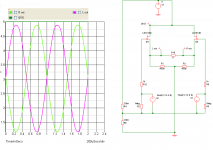

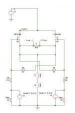
R14 and R15 are pulling the VGS of Q1 and Q2 down in a little, reducing the bias set point. Change the load resistor to 4 ohms and see if the clipping point changes.
Cheers, Terry
Cheers, Terry
I see what you mean: the addition of R14 and 15 cause the amp to clip harder under a four ohm load than without. I'll adjust the VGS point and see what happens.
Maybe I should call you "Ironman". 😀 In the movie, he's very smart (just like you)! 😀
Maybe I should call you "Ironman". 😀 In the movie, he's very smart (just like you)! 😀
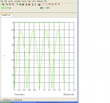
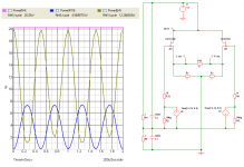
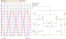
Amazing: bumping R3 & 4 to 8.2K brought the power consumption up to 118 watts and allows a full four ohm load!
Thanks a bunch for sharing, Terry!
edit: It also increased the output to 60 watts!! Wow. That's so efficient!
Thanks a bunch for sharing, Terry!
edit: It also increased the output to 60 watts!! Wow. That's so efficient!
- Status
- Not open for further replies.
- Home
- Amplifiers
- Pass Labs
- LU1014 differential amplifier