LTSPICE was wrong: MOSFET transconductance "gm" is NOT higher than bipolar gm
One of the MOSFET models that ships with LTSPICE, is for an Infineon device called IPP037N06L3. I simulated its transconductance "gm" in LTSPICE and found, to my great delight, that it was greater than the gm of a normal BJT power transistor. From the hybrid pi model we recall that bipolar gm = ICE / (kT/q) , sometimes written gm = ICE / vt where vt is the thermal voltage, 26 millivolts at room temperature.
Then I purchased the excellent "Intelligent Curve Tracer 3.0" sold by diyAudio member Locky_Z (link) and decided to actually measure the real MOSFET itself.
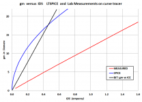
Figure 1 shows the simulated transconductance of the MOSFET, in blue. The BJT transconductance is the black trace. Hallelujah, MOSFET has higher gm right exactly in the region (200mA) where we want to operate it, as a series pass transistor in a Walt Jung Super Regulator for a linestage / preamp / headphone amp / etc. Unfortunately the real device, red curve, is not nearly as good.
Maybe the people who created the LTSPICE model of the IPP037N06L3, were more interested in the high current region (this FET is rated to carry 90 amperes) than the low current region. Maybe the VDMOS modeling equations themselves, are a poor approximation at low current. Whatever the explanation, the measured results don't match the simulations. And in particular, the red line (MOSFET) is below the black line (bipolar), meaning that MOSFET gm is less than bipolar gm. Quite a bit less.
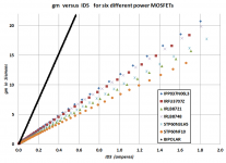
I purchased several other modern power MOSFETs whose datasheets indicated, they might have very high gm. And I measured them all using the Locky_Z curve tracer. The drain current measurements are shown in Figure 2, and the transconductance plots (gm = dIds/dVgs) are shown in Figure 3.
Again we see that bipolar (black curve in Figure 3) kicks butt compared to MOSFETs; its gm is far higher.
So, if you're interested in building a voltage regulator with a very low open loop output impedance (= 1/gm of the series pass transistor), choose a bipolar transistor rather than a MOSFET. Maybe someday, someone will build and sell MOSFETs whose measured gm exceeds bipolars. Maybe. Someday. But as far as I can tell, not today.
_
One of the MOSFET models that ships with LTSPICE, is for an Infineon device called IPP037N06L3. I simulated its transconductance "gm" in LTSPICE and found, to my great delight, that it was greater than the gm of a normal BJT power transistor. From the hybrid pi model we recall that bipolar gm = ICE / (kT/q) , sometimes written gm = ICE / vt where vt is the thermal voltage, 26 millivolts at room temperature.
Then I purchased the excellent "Intelligent Curve Tracer 3.0" sold by diyAudio member Locky_Z (link) and decided to actually measure the real MOSFET itself.
Figure 1 shows the simulated transconductance of the MOSFET, in blue. The BJT transconductance is the black trace. Hallelujah, MOSFET has higher gm right exactly in the region (200mA) where we want to operate it, as a series pass transistor in a Walt Jung Super Regulator for a linestage / preamp / headphone amp / etc. Unfortunately the real device, red curve, is not nearly as good.
Maybe the people who created the LTSPICE model of the IPP037N06L3, were more interested in the high current region (this FET is rated to carry 90 amperes) than the low current region. Maybe the VDMOS modeling equations themselves, are a poor approximation at low current. Whatever the explanation, the measured results don't match the simulations. And in particular, the red line (MOSFET) is below the black line (bipolar), meaning that MOSFET gm is less than bipolar gm. Quite a bit less.
I purchased several other modern power MOSFETs whose datasheets indicated, they might have very high gm. And I measured them all using the Locky_Z curve tracer. The drain current measurements are shown in Figure 2, and the transconductance plots (gm = dIds/dVgs) are shown in Figure 3.
Again we see that bipolar (black curve in Figure 3) kicks butt compared to MOSFETs; its gm is far higher.
So, if you're interested in building a voltage regulator with a very low open loop output impedance (= 1/gm of the series pass transistor), choose a bipolar transistor rather than a MOSFET. Maybe someday, someone will build and sell MOSFETs whose measured gm exceeds bipolars. Maybe. Someday. But as far as I can tell, not today.
_
Attachments

Well that blows. I wonder if it applies also to the NXP BUK9K3560E/BUK9K5260E which also modelled spectacularly well.
Buy an Intelligent Curve Tracer and find out! $229 on eBay. The curves shown in post #1 of this thread, are the very first ones I measured after power-on. Already I've gotten excellent value for money. BTW I also bought the competitor curve tracer from Syscomp, for more money, but this one is decidedly superior IMHO. I also own an old Tek 576 war horse, but it doesn't digitize the measured data and hand you a nice .CSV file.
I think my Peak Atlas DCA Pro can do this but it requires a Windows computer. I use a Mac. On my To Do list is to get a copy of Windows and run it with VMFusion. But it will likely take me awhile. Annoyingly I just sent an order to Mouser - I could have tacked a sample of each into that order.
Last edited:
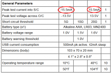
That's one of the few I didn't purchase. My reason was, that Atlas DCA Pro is battery powered and so it can only source or sink 15 milliamps into the Device Under Test. Syscomp can go up to 1 ampere and Locky_Z can go up to 3 amperes. Here is a table from the DCA Pro web page.
_
_
Attachments
Ok I see. I'm not sure I can justify the expense for now just to look at two parts. I note, however, those FETs are now available in the US from Mouser... 😉
I'd not come across Locky_z's curve tracer before but I see its available on Taobao, nice.
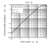
From studying many power MOSFET datasheets the highest gm I've found is only about 10% of a bipolar's at the same current - say at best 4S @ 1A. Toshiba makes the FETs with the highest gm, some of their small signal parts come as close as 50% of a bipolar's gm. Take the SSM3K123TU whose plot I've included here - at lowish currents (under 100mA) its doing about half of what a bipolar does.
@SGK - that BUK FET looks pretty good (but not as good as the Toshiba here), from eyeballing the datasheet the gm is about 8S @ 1A but notice its measured at 15V, in a regulator you'll probably have lower drop and hence lower gm.
Attachments
Last edited:
The curves in Figure 3 of post#1 show six MOSFETs whose gm is about 30% of the gm of a bipolar -- measured, not datasheet drawing. I recommend measuring this if at all possible; especially if you're using a high current transistor at 0.25 amps, I think you have many reasons to be skeptical of datasheet curves at low currents.
Last edited:
The Infineon's vital stats are jolly impressive - however the high gm for the drain current doesn't look to be sustained at higher currents, the steepest part of the curve is below 5A.
I agree that measurements trump datasheets, I shall be looking to invest in one of Locky's devices. What software does he supply with it - as its USB does it come with a driver?
I agree that measurements trump datasheets, I shall be looking to invest in one of Locky's devices. What software does he supply with it - as its USB does it come with a driver?
First generation Locky_Z curve tracer was RS232 serial.
Second generation was switch selectable: either RS232 or USB, using the infamous Prolific PL2303 chip {WIDELY copied / counterfeited} and drivers
Third (current) generation uses only USB, with the Prolific PL2303 and its drivers. It took me less than 48 hours to perform enough trial-and-error experiments, to find an arrangement and a set of voodoo incantations which made this work. On my Windows PC with my motherboard and with my peripherals and with my version(s) of software and drivers.
But now it does work and I am very pleased with the results. If you've ever written a Windows application that talks to external hardware, you will immediately "grok" the software interface.
Ummmmm...
How are you determining the mosfet transconductance? You mentioned gm=dIDs/dVgs, that's flat wrong, it applies only in the linear region and up to incipient saturation.
Saturation is the normal operating region for mosfets (nothing to do with bipolar saturation). In saturation, given an Id vs. Vgs measurement, the right way to determine the transconductance as a function of Ids is: for each Ids calculate gm=2*Ids/(Vgs-Vt) where Vgs is the gate-source voltage for Ids, and Vt is the mosfet threshold voltage. For power devices, Vt is usually defined as the voltage at which the drain current is 250uA. It's specified in the data sheet, but the limits are usually very large (e.g. 3...6V) so you need to determine it for each device under test.
In a first approximation, you need to double the gm values you got, to make an apple to apple comparison with bipolars.
Last edited:
It's not out of the question that the models fit the high current performance but need for charge conservation reasons to smoothly go to zero at the origin just so SPICE does not break.
Are these pulse or dc measurements? The Vgs negative temperature coefficient makes the mosfet VGs/Id curve look much steeper than it really is, as the device gets hot at higher currents
Thank you for that piece of wisdom. I have saved it for posterity in the image file below. Even after you get banned, or drop out, or just lose interest, it's preserved here forever more. And I will cherish it. Thank you.You mentioned gm=dIDs/dVgs, that's flat wrong.
Attachments
Are these pulse or dc measurements?
Anybody who has done both, themselves, personally, can see just by observing the shape of the curves, that these measurements are performed with low duty cycle pulses.
Sure. I'm simply reporting some DATA, nothing more and nothing less. This is what you get from LTSPICE, this is what you get from measurement, this is what you get from the hybrid pi model. If someone wants to "spin" the data a certain way, let em. Just remember that data and spin are two different things.It's not out of the question that the models fit the high current performance but need for charge conservation reasons to smoothly go to zero at the origin just so SPICE does not break.
Yes, we all know since very long time ago that mosfets have issues in the modelling development for SPICE.
May be it is the reason why some people design VMOSFET amps with low current. It looks good in LTSpice but doesn't sound good in reality.
I think it is obvious with MOSFETs, but how about BJT models? Because I think I have experienced similar issue with BJT in VAS position. LTSpice shows very good performance with low bias current (C1381, C1360 and the like) which I strongly believe is not the case in reality.
I am a former developer of integrated circuits. In particular manufactured in CMOS technology. I had to develop micro-power generators and stabilizers. I know that most of the models of MOS transistors lie heavily at small (relative to nominal) currents. For digital (switch) schemes is not terrible. Characteristics of MOS transistors Immersed two voltage region on the gate . This is a common area (approximately square law) and subthreshold (exponential law).
The exponential law Id = i0 * exp (Vgs / (n * vt), n> 1 ~ (1.5-5)
==> Gm=Id/(n * vt), vt=26mV.
LTspice in VDMOS model it is possible to use the sub-threshold region.
The exponential law Id = i0 * exp (Vgs / (n * vt), n> 1 ~ (1.5-5)
==> Gm=Id/(n * vt), vt=26mV.
LTspice in VDMOS model it is possible to use the sub-threshold region.
- Status
- Not open for further replies.
- Home
- Amplifiers
- Solid State
- LTSPICE was wrong: MOSFET transconductance "gm" is NOT higher than bipolar gm