I just started to build class A USSA-5 power amp and I am in need for a good CRC power supply. Which version should I get for this application? I plan to get 2 CRC PCBs.

This is very interesting, thank you @prasi for the work and for sharing all documentation.
I am building some of my own with the LT4320 controller and am wondering about mosfet selection. The mosfets listed in the schematic (I looked at the Toshiba ones) vary in power dissipation capability, with somewhat varying Rdson and Qg values. The lower the better it seems, but as Rdson goes down the Qg appears to go up a bit and vice versa.
What are the most important physical selection criteria for very low current applications? (For example a phono preamp.) Or are all listed alternatives functionally interchangeable and are price and availability the only limiting factors?
In this here thread the OP has embarked on a similar project and ended up with a webshop that sells rectifiers that are both pretty and expensive. In one of the early posts someone refers to what looks like this here thread about using a GaN device instead of regular silicon based mosfets. Total Qg is extremely low and in Japan some forum members seem pretty happy with these. The aforementioned web shop also carries a very pricy alternative with GaN transistors.
I reproduced the LTspice model shown at this here Japanese blog and it works just fine. So technically, it would be an option. However, at $8.50 a piece at Mouser the equipment quickly becomes very expensive (LT4320 isn't exactly cheap either), so I will stick with Toshiba Si based mosfets.
Still, I would much appreciate some guidance on the choice of switching device - between the listed Toshiba Si-based mosfets but also if a GaN adds real-world benefits.
please PM me and I will share sch and stuffing guide. I think its one of those sponsored designs.
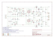
It’s because 22 indicates the peak value of voltage source V1, not the RMS value. A spice quirk.
I infer from this that if I have a transformer with a voltage of 22V AC, then to simulate this voltage in LTspice I must specify 31.1V as input voltage(22 × √2 = 31.1 V).Am I understanding this correctly?It’s because 22 indicates the peak value of voltage source V1, not the RMS value. A spice quirk.
Dear Prasi,
I need help!
I bought 8pcs LT4320 C-R-C PSU Pcb. I would like to know what can replace the R2 resistors 684-MP821-0.02 price 14 euro/pc?
Another problem I have is what voltage transformer should I use if I want to use a PSU with irregular voltage after the LT4320 C-R-C PSU.
The PSU connected after it is Q17 Sigma PSU by Steff.
The output voltage of this PSU is 54 V. Can you help me?
The amplifier that drives this is Q17
Best Regards
Andrew from Hungary
Attachments
i build 2 of Prasi PCBs. I used 47000 capacitors. I use 18V x2 300VA toroidals. When I measure the output voltage with no load, one board shows equal numbers. Second board shows -25.97Vdc and the other side shows +24.76Vdc. I switched the 18v transformer windings and still same value. Could be one of the MOSFET defective? I got them from Mouser and are supposed to be genuine. Any advice on how to troubleshoot this issue?
Attachments
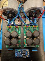
Without a load connected to the output, the voltages won’t be accurate.
- Home
- Group Buys
- LT4320 based active rectifier