Thank you! Will add it to my prefered FET's list. (which is a few)
There are also SIR626DP-T1-RE3 Vishay / Siliconix | Mouser , the same FET but whithout top side cooling feature, less heat tranfer, cheaper.
It seems Mouser specification on this FET is not correct but datasheet PDF is correct.
Although I like more idea of top side cooling. 🙂
Dear all,
Sheet is updated to reflect the current status of availability of paypal and addresses.
group list qty_new - Google Sheets
regards
Prasi
Sheet is updated to reflect the current status of availability of paypal and addresses.
group list qty_new - Google Sheets
regards
Prasi
Been away and I must have missed something😕
I should provide my PayPal and shipping address to you by PM or how does it work?
I should provide my PayPal and shipping address to you by PM or how does it work?
Dear all,
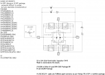
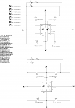
Here is the schematics THT and SMD boards.
I have given a rough indication of type of MOSFETS suitable for the application.
While this isnt a strict requirement use particular mosfet, do follow the guidelines given in the below post by me .
LT4320 based active rectifier
and very comprehensively by Tibi
LT4320 based active rectifier
I still would like to retain the optional pads for electro cap just in case of someone's implementation makes it far away from main filter caps.
Also, retained is the optional led indicator for smd, but I would recommend LED+ resistor only for low-medium voltage application (12-35V) where dissipation through resistor can be controlled well within the rated power. https://www.mouser.in/datasheet/2/392/n_catalog_partition24_en-948804.pdf
As informed by Tibi, there no absolute need for either electro cap or LED indicator.
Regards
Prasi
Attachments
Prasi, I am ready for payment if you are. 🙂
By the way your private messages quota is full.
By the way your private messages quota is full.
Last edited:
Hello Rainfallsky,
At an appropriate time when the boards are about to be delivered , I will send out a Paypal invoice to every subscriber. Thats when one needs to make the payment.
Inbox is now good to go. Sorry for the inconvenience.
Regards
Prasi
P.S. 500 PM storage capacity and still it gets full. I need to find a way to retrieve DIYA xml export so that I can refer old PMs when required.
Thank you Cerole and others for sending me address and paypal details
I have updated the sheet.
To members: As can be seen from the sheet , THT pairs are all booked. But 41 SMD pairs still remain. Please book it as soon as possible.
group list qty_new - Google Sheets
regards
Prasi
I have updated the sheet.
To members: As can be seen from the sheet , THT pairs are all booked. But 41 SMD pairs still remain. Please book it as soon as possible.
group list qty_new - Google Sheets
regards
Prasi
Ok, thanks for address and PayPal details and updating the sheet.
Delivery is expected to be in another 18 work days.
Then I shall start sending out invoices and shipping.
Delivery is expected to be in another 18 work days.
Then I shall start sending out invoices and shipping.
Hi prasi, can you add details for R and C values on the through hole schematic you have shown at post 165, thanks.
Last edited:
Actually those are nothing but quasimodo transformer snubbers to be determined for a given transformer via quasimodo procedure detailed by Mark Johnson.
Simple, no-math transformer snubber using Quasimodo test-jig
The values shown on SMD schema are arbitary and needs to be determined too.
regards
Prasi
Simple, no-math transformer snubber using Quasimodo test-jig
The values shown on SMD schema are arbitary and needs to be determined too.
regards
Prasi
Though I am no EE, I understand Snubber is for transformer.
The following excellent documentation by Mark Johnson does provide some insights
https://www.diyaudio.com/forums/att...ing-quasimodo-test-jig-quasimodo_jig_reva-pdf
(page 5 is important)
The following excellent documentation by Mark Johnson does provide some insights
https://www.diyaudio.com/forums/att...ing-quasimodo-test-jig-quasimodo_jig_reva-pdf
(page 5 is important)
Last edited:
I am not EE too just trying to understand things in a subject where I floating. )
But snubber is definately for dumping transformer secondary so it wont ring.
I just remembered Mark Johnson article in Linear Audio where he tests a lot of diodes.
Introduction was that in PSU diode switch-off generates a current spikes (dl/dt).
Large spikes stimulate transformer oscillatory ringing. (very simplified)
Part of conclusion was that in the end all diodes more or less produce transformer ringing. (thats how I understand it)
What I wanted to ask, does LT4320+FETs active rectifier produce same thing (ringing)?
LT4320 +FET is free from so called diode switching noise as posted by tvicol.
Ideal bridge rectifier GB
Ideal bridge rectifier GB
Last edited:
That's my understanding too. The switching generates a lot of heat. Anyone has more opinions or comments to further our understand?
Regards,
Regards,
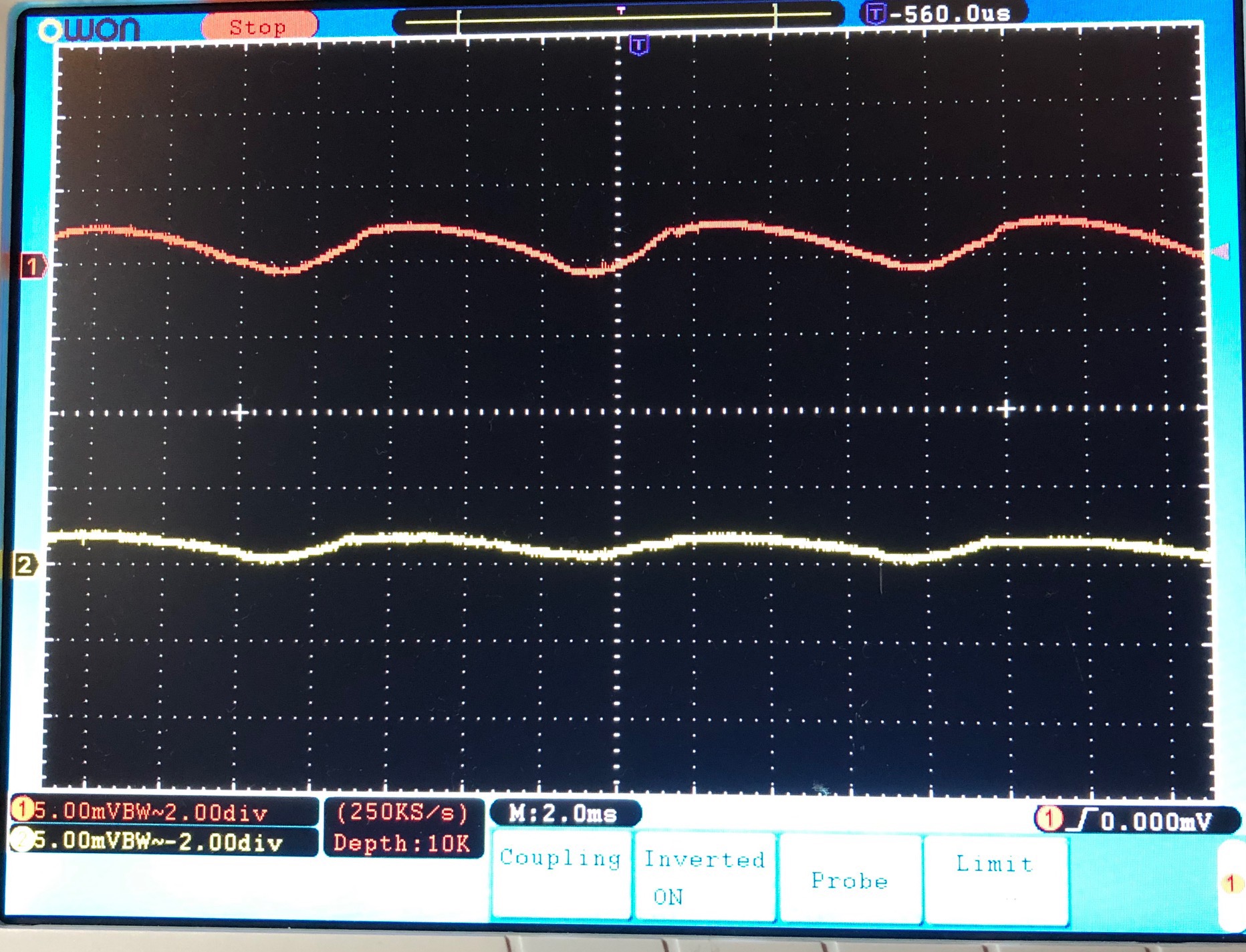
On the SLB PSU which uses the LT4320, the rectified output is a clean sawtooth with no switch noise or ringing - this is because the MOSFETs are time phased to switch at zero crossover. Whereas diodes switch at 0.6v. There is also minimal heat if low RDson MOSFETs are used. I measure 35C for 4.4A current with no heatsinks. If the active bridge is used with a properly designed CRC (note that you do *not* want low ESR caps here to reduce the ripple current which can overheat a bulk cap). and in my case 15,000uF // 0.2R // 15,000uF and a CFP Cap MX, the output ripple was measured at sub mV rms for 4A SE Class A amp load. See yellow trace below. After seeing measured performance of the LT4320 and hearing how clean it sounds, plus fact that it generates no heat - the classic Si diode bridge is dead to me for high current Class A applications. There is no going back - It is just better in every way. I have a bunch of CRC and CRCRC PSU boards that use TO220 diodes. Not sure if I will ever use them now unless I adapt them to use LT4320 active bridge.
Last edited:
Thank you x for the info and results.
If the CRC / CRCRC are supplied by me , then following can be done.
CRCRC has pads for smd active bridge, so you can use them. I had sent you some SMD
boards I think.
If the CRC / CRCRC are supplied by me , then following can be done.
CRCRC has pads for smd active bridge, so you can use them. I had sent you some SMD
boards I think.
- Home
- Group Buys
- LT4320 based active rectifier