Cheers for this Prasi,
A bit of a newbie to this area, so looking for feedback on post #1537 above
Planning on using:
584-LT4320IN8-1#PBF
757-TPH1R306PL1LQ mosfets if singles pcb
78-SQJB00EP-T1_GE3 mosfets if doubles pcb
https://www.mouser.com/ProductDetail/80-C0805C105J3RACTU
80-C0805C105J3RACTU resistors
327-VFR1105WTR LEDs, if I put them in
Any thoughts or opinions?
Cheers
Last edited:
Planning on using:
584-LT4320IN8-1#PBF this is ok.
757-TPH1R306PL1LQ mosfets if singles pcb - this is ok, but see if you can find something with lower Qg. Rdson of 3-5mOhm or 7 mOhm is also ok
78-SQJB00EP-T1_GE3 mosfets if doubles pcb- not compatible with my SMD pcbs shipped to you.
https://www.mouser.com/ProductDetail/80-C0805C105J3RACTU this is ok. but see if you can find 1210 size. you can go up in value also say 4.7uF
80-C0805C105J3RACTU resistors - this is the same cap.
327-VFR1105WTR LEDs, if I put them in - ok. see if you can find 1210 size.
LED resistor should also be 1210 size..
Any thoughts or opinions?

Lets make a list and see if we run into enough numbers to make another bulk order
1. CRC PSU PCB IN SINGLES
2. THT RECTIFIER IN PAIRS
danbmellow - 4 PAIRS
3. SMD RECTIFIER IN PAIRS
1. CRC PSU PCB IN SINGLES
2. THT RECTIFIER IN PAIRS
danbmellow - 4 PAIRS
3. SMD RECTIFIER IN PAIRS
I’ll help with the THT Rectifiers!
1. CRC PSU PCB IN SINGLES
2. THT RECTIFIER IN PAIRS
danbmellow - 4 PAIRS
Uptownsquash - 20 PAIRS
3. SMD RECTIFIER IN PAIRS
1. CRC PSU PCB IN SINGLES
2. THT RECTIFIER IN PAIRS
danbmellow - 4 PAIRS
Uptownsquash - 20 PAIRS
3. SMD RECTIFIER IN PAIRS
1. CRC PSU PCB IN SINGLES
Uptownsquash - 2 nos
2. THT RECTIFIER IN PAIRS
danbmellow - 4 PAIRS
Uptownsquash - 20 PAIRS
3. SMD RECTIFIER IN PAIRS
prices are SR. 1 is 6.5 USD PER PIECE, SR. 2 is 3.5USD PER PAIR, SR. 3 is 2.5 USD PER PAIR
Uptownsquash - 2 nos
2. THT RECTIFIER IN PAIRS
danbmellow - 4 PAIRS
Uptownsquash - 20 PAIRS
3. SMD RECTIFIER IN PAIRS
prices are SR. 1 is 6.5 USD PER PIECE, SR. 2 is 3.5USD PER PAIR, SR. 3 is 2.5 USD PER PAIR
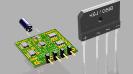
There's an LT4320 Active Rectifier PCB for sale on EBay @£2.95 each, discount for multi-buy.
https://www.ebay.co.uk/itm/14563729...uid=YiMsmhofQW2&widget_ver=artemis&media=COPY
UK based. description is:
LT4320/LT4320-1 Active Rectifier PCB, 4x MOSFET Bridge Rectifier, "Ideal Diode" blank PCB.
Bare PCB to make an active bridge rectifier using 4-off N-channel MOSFET and LT4320 or LT4320-1.
Forward voltage drop typically less than 0.2vdc. Input range 9v to 72v. Ig = 1.5mA.
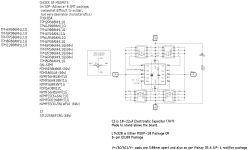
The board is configured for 4-off DPAK-3 N-channel MOSFETS, such as FDD10ANO6AO or similar. LT4320/-1 is MSE PACKAGE 12-LEAD PLASTIC MSOP.
Essential where low-loss conversion is required. Also acts as "polarity agnostic" power connector, ie any polarity at the input will always give correct + and - polarity at output.
The LT4320/LT4320-1 are ideal diode bridge controllers that drive four N-channel MOSFETs, supporting voltage rectification from DC to 600Hz typical. By maximizing available voltage and reducing power dissipation, the ideal diode bridge simplifies power supply design and reduces power supply cost, especially in low voltage applications.
An ideal diode bridge also eliminates thermal design problems, costly heat sinks, and greatly reduces PC board area. The LT4320’s internal charge pump supports an all- NMOS design, which eliminates larger and more costly PMOS switches. If the power source fails or is shorted, a fast turn-off minimizes reverse current transients.
The LT4320 is designed for DC to 60Hz typical voltage rectification, while the LT4320-1 is designed for DC to 600Hz typical voltage rectification. Higher frequencies of operation are possible depending on MOSFET size and operating load current.
https://www.ebay.co.uk/itm/14563729...uid=YiMsmhofQW2&widget_ver=artemis&media=COPY
UK based. description is:
LT4320/LT4320-1 Active Rectifier PCB, 4x MOSFET Bridge Rectifier, "Ideal Diode" blank PCB.
Bare PCB to make an active bridge rectifier using 4-off N-channel MOSFET and LT4320 or LT4320-1.
Forward voltage drop typically less than 0.2vdc. Input range 9v to 72v. Ig = 1.5mA.
The board is configured for 4-off DPAK-3 N-channel MOSFETS, such as FDD10ANO6AO or similar. LT4320/-1 is MSE PACKAGE 12-LEAD PLASTIC MSOP.
Essential where low-loss conversion is required. Also acts as "polarity agnostic" power connector, ie any polarity at the input will always give correct + and - polarity at output.
The LT4320/LT4320-1 are ideal diode bridge controllers that drive four N-channel MOSFETs, supporting voltage rectification from DC to 600Hz typical. By maximizing available voltage and reducing power dissipation, the ideal diode bridge simplifies power supply design and reduces power supply cost, especially in low voltage applications.
An ideal diode bridge also eliminates thermal design problems, costly heat sinks, and greatly reduces PC board area. The LT4320’s internal charge pump supports an all- NMOS design, which eliminates larger and more costly PMOS switches. If the power source fails or is shorted, a fast turn-off minimizes reverse current transients.
The LT4320 is designed for DC to 60Hz typical voltage rectification, while the LT4320-1 is designed for DC to 600Hz typical voltage rectification. Higher frequencies of operation are possible depending on MOSFET size and operating load current.
Thanks, Prasi,yes, that should work.
All boards arrived well.
Looks good, and thanks for the support.
To help further along this GB….
1. CRC PSU PCB IN SINGLES
Uptownsquash - 2 nos
2. THT RECTIFIER IN PAIRS
danbmellow - 4 PAIRS
Uptownsquash - 20 PAIRS
3. SMD RECTIFIER IN PAIRS
Uptownsquash - 10 PAIRS
prices are SR. 1 is 6.5 USD PER PIECE, SR. 2 is 3.5USD PER PAIR, SR. 3 is 2.5 USD PER PAIR
1. CRC PSU PCB IN SINGLES
Uptownsquash - 2 nos
2. THT RECTIFIER IN PAIRS
danbmellow - 4 PAIRS
Uptownsquash - 20 PAIRS
3. SMD RECTIFIER IN PAIRS
Uptownsquash - 10 PAIRS
prices are SR. 1 is 6.5 USD PER PIECE, SR. 2 is 3.5USD PER PAIR, SR. 3 is 2.5 USD PER PAIR
I guess 100/200 pairs of rectifier PCBs and 30-50 of the CRC PCBs.
However I wait only for week and then order the stuffs, because I keep getting intermittent requirements all through the year.
However I wait only for week and then order the stuffs, because I keep getting intermittent requirements all through the year.
I will take 4 more CRC Boards and an additional 2 pairs of the THT rectifiers.
1. CRC PSU PCB IN SINGLES
Uptownsquash - 2 nos
danbmellow 4 - nos
2. THT RECTIFIER IN PAIRS
danbmellow - 6 PAIRS
Uptownsquash - 20 PAIRS
3. SMD RECTIFIER IN PAIRS
Uptownsquash - 10 PAIRS
prices are SR. 1 is 6.5 USD PER PIECE, SR. 2 is 3.5USD PER PAIR, SR. 3 is 2.5 USD PER PAIR
1. CRC PSU PCB IN SINGLES
Uptownsquash - 2 nos
danbmellow 4 - nos
2. THT RECTIFIER IN PAIRS
danbmellow - 6 PAIRS
Uptownsquash - 20 PAIRS
3. SMD RECTIFIER IN PAIRS
Uptownsquash - 10 PAIRS
prices are SR. 1 is 6.5 USD PER PIECE, SR. 2 is 3.5USD PER PAIR, SR. 3 is 2.5 USD PER PAIR
1. CRC PSU PCB IN SINGLES
Uptownsquash - 2 nos
danbmellow 4 - nos
jdoorn - 6
2. THT RECTIFIER IN PAIRS
danbmellow - 6 PAIRS
Uptownsquash - 20 PAIRS
3. SMD RECTIFIER IN PAIRS
Uptownsquash - 10 PAIRS
jdoorn - 8 pairs
prices are SR. 1 is 6.5 USD PER PIECE, SR. 2 is 3.5USD PER PAIR, SR. 3 is 2.5 USD PER PAIR
Uptownsquash - 2 nos
danbmellow 4 - nos
jdoorn - 6
2. THT RECTIFIER IN PAIRS
danbmellow - 6 PAIRS
Uptownsquash - 20 PAIRS
3. SMD RECTIFIER IN PAIRS
Uptownsquash - 10 PAIRS
jdoorn - 8 pairs
prices are SR. 1 is 6.5 USD PER PIECE, SR. 2 is 3.5USD PER PAIR, SR. 3 is 2.5 USD PER PAIR
Hi Prasi
Could you please add a picture associated with each of the 3 items ?
78 pages in very long to go through and I want to make sure I’ll order the correct items
Thanks
Eric
Could you please add a picture associated with each of the 3 items ?
78 pages in very long to go through and I want to make sure I’ll order the correct items
Thanks
Eric
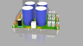
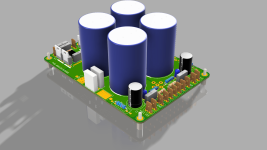
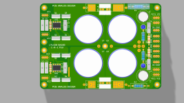
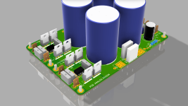
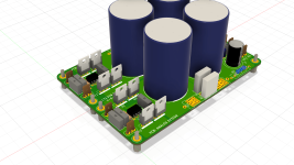
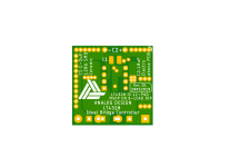
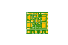
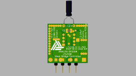
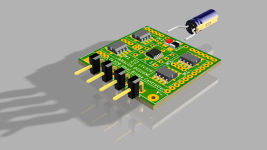
SMD LT4320
Attachments
-
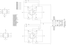
 sch-smd-new.png103.6 KB · Views: 320
 -
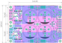
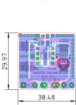 smd-new-DIMS-ALL LAYERS.png41.6 KB · Views: 308
 -
 2D-btm-SMD.png52.1 KB · Views: 230
 -
 2D-top-SMD.png47.8 KB · Views: 219
 -
 3D-SMD-BTM.png33 KB · Views: 213
 -
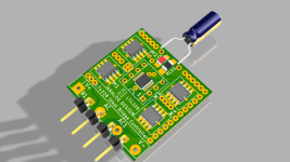 3D-SMD-ISO.png123.5 KB · Views: 220
 -
 3D-SMD-ISO-.png126.7 KB · Views: 236
 -
 3D-SMD-ISO-2.png110.1 KB · Views: 237
 -
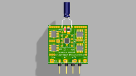 3D-SMD-TOP.png43.2 KB · Views: 317
- Home
- Group Buys
- LT4320 based active rectifier