I've been SPICE modeling what (to me) is a new version of the well-known "Linkwitz Transform" biquadratic filter that includes a boost limiter (not a volume limiter). My circuit uses a different type of biquadratic filter circuit than what SL uses. It still has a single op amp to create the filter itself, but since the response of the filter can not provide boost (only cut) it is followed by a gain stage.
It turns out that the shape, specifically the low frequency boost, can be modulated. A detection circuit looks at the final output signal and when it exceeds some threshold the low frequency boost of the biquad filter is reduced (at low frequencies) while the high frequency gain remains unchanged. This permits the power of the amplifier and the driver excursion capability to be used more efficiently. At low input signal level the lowest frequencies are boosted as much as possible, up to the full power input level for the amp, and as the input signal level is raised the LF boost is tapered off. This is done without introducing extreme distortion at the expense of reducing/compressing the output at the lowest frequencies on peaks.
About the only similar thing I have seen out there is a circuit (US Patent 4481662, download at PAT2PDF - Free PDF copies of patents: Download and print!) by Bag End for their ELF subwoofer line that used a double integrator type of boost circuit, with a limiter. Supposedly the ELF systems were pretty well received. My approach is related in theory, but is implemented differently.
As part of the modeling that I have done, I've looked at the distortion under dynamic signal conditions and it looks to be no more than -40dB, sometimes below -60dB dominated by 2nd order and falling off quickly. The driver will probably exhibit much more distortion.
Anyway, is this really something new? I have some PCBs already made that I can build up and test if there is enough interest. I would also be willing to post some modeling results.
-Charlie
Watching with interest - if you get it working nicely, I think you might be able to sell a few boards.
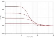
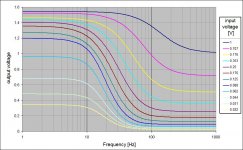
The attachment shows an example of the boost reduction that the circuit can achieve with increasing input level, so as to keep the max output level from exceeding a threshold. The "flattest" curve corresponds to the highest input level, while the curve with the highest low frequency gain corresponds to the lowest input level.
It's not perfect in that it also slightly alters the filter shape, but it's only by about 2dB or less at the upper knee in the response, and is IMO low enough to not worry about.
-Charlie
It's not perfect in that it also slightly alters the filter shape, but it's only by about 2dB or less at the upper knee in the response, and is IMO low enough to not worry about.
-Charlie
Attachments
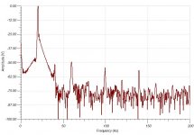
Attached is an example of the distortion spectrum under very strong boost limiting conditions for a 20Hz tone burst. Distortion components are -50 or better (fundamental is slightly off scale and is about +2dB). Note, this is SPICE modeling using TINA, not a "real world" circuit.
Edit: I should add that when I obtain the same spectrum on the stimulus (input signal) I get similar distortion numbers, so it looks like the circuit does not add much distortion.
Edit: I should add that when I obtain the same spectrum on the stimulus (input signal) I get similar distortion numbers, so it looks like the circuit does not add much distortion.
Attachments
Last edited:
If I am reading this correctly it sounds like you have something that I was looking for many months ago. If I remember correctly Don Hills was looking at the idea. I wanted something that would boos the low end of two Beta 15As in an open baffle at lower volume levels but would reduce that boost as the volume was turned up and therefore hopefully preventing the the Eminences exceeding xmax too much as the volume was increased. Will this circuit you have developed do that? jamikl
If I am reading this correctly it sounds like you have something that I was looking for many months ago. If I remember correctly Don Hills was looking at the idea. I wanted something that would boos the low end of two Beta 15As in an open baffle at lower volume levels but would reduce that boost as the volume was turned up and therefore hopefully preventing the the Eminences exceeding xmax too much as the volume was increased. Will this circuit you have developed do that? jamikl
Yes, that's it exactly. I will try to post additional plots that make this more clear.
-Charlie
Charlie,I've been SPICE modeling what (to me) is a new version of the well-known "Linkwitz Transform" biquadratic filter that includes a boost limiter (not a volume limiter)
About the only similar thing I have seen out there is a circuit (US Patent 4481662, download at PAT2PDF - Free PDF copies of patents: Download and print!) by Bag End for their ELF subwoofer line that used a double integrator type of boost circuit, with a limiter. Supposedly the ELF systems were pretty well received. My approach is related in theory, but is implemented differently.
Anyway, is this really something new?
Sounds like what can be done with the dynamic EQ in the Behringer Ultradrive Pro DCX2496.
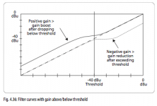
"The DYNAMIC EQ influences a specific frequency range of the signal, depending on the volume level. It can either boost or cut this frequency range, depending on the gain setting made by the user. If the gain control is set to lower the respective frequency range in level, and if a preset THRESHOLD is exceeded, the EQ modifies the sound by reducing the gain of the frequency range. The amount of gain reduction applied is defined by the RATIO value. When the signal drops below threshold again, the frequency range is “smoothed out” again, i.e. the DYNAMIC EQ stops processing the signal."
Unlike the Bag End device which is fixed for a single application, the DCX2496 can be adjusted for any desired boost/cut frequencies and thresholds.
Art
Attachments
also available in sigma studio for powersoft dsp board(dynamic bass).
sort of loudness for the lowes🙂
sort of loudness for the lowes🙂
Very nice idea and is probably of great interest to the OB crowd. I know I sometimes worry about my woofers bottoming out when wanting to really crank out the tunes.
Additionally, this circuit would help with the "best response curve for hearing" that I found a few years ago.
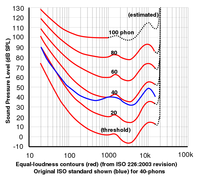
Additionally, this circuit would help with the "best response curve for hearing" that I found a few years ago.
Charlie,
Sounds like what can be done with the dynamic EQ in the Behringer Ultradrive Pro DCX2496.
"The DYNAMIC EQ influences a specific frequency range of the signal, depending on the volume level. It can either boost or cut this frequency range, depending on the gain setting made by the user. If the gain control is set to lower the respective frequency range in level, and if a preset THRESHOLD is exceeded, the EQ modifies the sound by reducing the gain of the frequency range. The amount of gain reduction applied is defined by the RATIO value. When the signal drops below threshold again, the frequency range is “smoothed out” again, i.e. the DYNAMIC EQ stops processing the signal."
Unlike the Bag End device which is fixed for a single application, the DCX2496 can be adjusted for any desired boost/cut frequencies and thresholds.
Art
I have owned a couple of DCX2496 units but never made use of this feature. One problem is that the closest function is the second order shelf, but that is not as flexible in the shapes that it can take on compared to the various shapes of a closed box speaker. You could add on additional EQ bands to mimic the response around resonance of the speaker (e.g. if peaking). You are correct in that the DCX would be adjustable and my circuit can be built in different ways but is not adjustable afterwards.
In any case, while there might be a $300 solution I think that a couple of analog circuit boards can do the same thing for much less. And it makes for something that you can built into the speaker (for a subwoofer or the woofer in a 3-way, for instance) and I personally build speakers that way, with amps and electronics built in so it works nicely for my needs.
-Charlie
Attached is another plot that shows what is going on with my "boost limiting" circuit. The input was a dynamic burst at 10Hz, with various input levels.
The plot shows the peak output voltage and the corresponding gain (Vout/Vin) for the 10Hz signal, in decibels. At the lowest input voltage, the full gain is available. As input voltage increases so that the output rises to 1.5V the gain is dialed back so that the peak output voltage does not exceed the 1.5V limit/threshold. The 1.5V value is just an arbitrary value I picked and is adjustable via a pot. This kind of response to varying input levels is useful for not driving the amp into clipping, which would result in lots of audible harmonics and other distortion.
Will follow up with a plot of the variable gain versus frequency later...
-Charlie
Attachments

Attached is a plot of the output voltage as a function of frequency for a variety of input levels. As before, this data was obtained on a 10Hz burst input signal, the max level of which was varied. This more clearly shows the change in boost.
-Charlie
-Charlie
Attachments
A little update on this effort:
I've been doing several iterations on the circuitry that monitors the output level and controls the feedback signal that reduces the boost. I've finally come up with something that has variable controls for:
There are some tradeoffs in this kind of design approach - the attack rate, decay rate, and feedback gain are somewhat interrelated. Attack and decay rates are related to the low frequency limit of operation and so are dependent on the particular application. When operating the circuit with high feedback gain you get very good control of the output voltage and it will not exceed the voltage limit setpoint but for the lowest frequencies there is some pumping that can be observed when the signal period starts approaching the decay time constant. If you reduce the feedback gain the pumping goes away, and if you continue to decrease the gain the limiting action becomes "softer". By making the feedback gain adjustable, the tradeoff that works the best can be left up to the end user.
In the case that "soft" limiting is preferred and/or the user wants to make sure that the output eventually hits a "hard" limit I decided to include a diode shunt limiter on the output. The level at which the diodes start conducting is biased along with the setpoint for the output voltage gain, so that both are controlled in tandem from one setting. For instance if the output voltage gain is set to 2V the diodes will start conducting at around 2.5V and then will clip hard at 2.7V or so. If the output voltage gain is changed to 1V the diodes will start conducting at around 1.5V and then will clip hard at 1.7V or so.
In my modeling I have observed (for low feedback gain) that on some signals the first few cycles of the burst that I am using to test is not sufficiently limited but subsequent output is limited below the setpoint, and the hard limiter seems to be a good way to deal with these brief output surges and prevent the amp from seeing too high an input signal. Again, this type of brief overshoot can also be eliminated by increasing the feedback gain, but for some low-gain settings this seems to be a good secondary measure for limiting the output voltage.
Anyway, that's the latest report of progress on the design. I'll try to post some examples of the limiting behavior but might not get to it for a couple of days.
-Charlie
I've been doing several iterations on the circuitry that monitors the output level and controls the feedback signal that reduces the boost. I've finally come up with something that has variable controls for:
- output voltage limit
- feedback gain
- attack rate of boost limiter
- decay rate of boost limiter
There are some tradeoffs in this kind of design approach - the attack rate, decay rate, and feedback gain are somewhat interrelated. Attack and decay rates are related to the low frequency limit of operation and so are dependent on the particular application. When operating the circuit with high feedback gain you get very good control of the output voltage and it will not exceed the voltage limit setpoint but for the lowest frequencies there is some pumping that can be observed when the signal period starts approaching the decay time constant. If you reduce the feedback gain the pumping goes away, and if you continue to decrease the gain the limiting action becomes "softer". By making the feedback gain adjustable, the tradeoff that works the best can be left up to the end user.
In the case that "soft" limiting is preferred and/or the user wants to make sure that the output eventually hits a "hard" limit I decided to include a diode shunt limiter on the output. The level at which the diodes start conducting is biased along with the setpoint for the output voltage gain, so that both are controlled in tandem from one setting. For instance if the output voltage gain is set to 2V the diodes will start conducting at around 2.5V and then will clip hard at 2.7V or so. If the output voltage gain is changed to 1V the diodes will start conducting at around 1.5V and then will clip hard at 1.7V or so.
In my modeling I have observed (for low feedback gain) that on some signals the first few cycles of the burst that I am using to test is not sufficiently limited but subsequent output is limited below the setpoint, and the hard limiter seems to be a good way to deal with these brief output surges and prevent the amp from seeing too high an input signal. Again, this type of brief overshoot can also be eliminated by increasing the feedback gain, but for some low-gain settings this seems to be a good secondary measure for limiting the output voltage.
Anyway, that's the latest report of progress on the design. I'll try to post some examples of the limiting behavior but might not get to it for a couple of days.
-Charlie
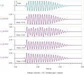
Attached are a couple of examples of the output of the circuit, given a single frequency (10 Hz) "burst" input.
The first attachment shows the response to increasing input level, with a max output level set to 1.5V. Even up to 1V input, when the gain at 10Hz has been reduced from 24dB to about 4dB, the signal shape is still pretty clean. Not shown is the distortion levels, which are about 1% dominated by 3rd order. There is some evidence of pumping for the Vmax=0.2V input level, but this amounts to only about 2-3dB difference in level.
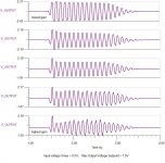
The second attachment shows a range of feedback gain settings for an input level of 0.5V. At the lowest gain setting, the boost limiter is barely working and the limiting is coming from the diode shunt limiter on the output, causing distortion to be about 14%. As gain in increased (moving down the figure), the distortion levels are 0.5%, 1.25%, 3%, and 5% respectively. Pumping is visually evident in the bottom trace. At the same time, there is a tradeoff in the limiting action - the levels increasingly falling within the 1.5V output voltage setpoint. While the trace second from the top has the lowest distortion, output amplitude is greater than 1.5V but less than the level at which the diode limiter is clipping the output. The gain could be increased or the output voltage setpoint could be reduced slightly.
One note - these results are for 10Hz, which shows the pumping effects the most. Higher frequencies have slightly different behavior but I have not had the time to fully investigate it yet.
-Charlie
The first attachment shows the response to increasing input level, with a max output level set to 1.5V. Even up to 1V input, when the gain at 10Hz has been reduced from 24dB to about 4dB, the signal shape is still pretty clean. Not shown is the distortion levels, which are about 1% dominated by 3rd order. There is some evidence of pumping for the Vmax=0.2V input level, but this amounts to only about 2-3dB difference in level.
The second attachment shows a range of feedback gain settings for an input level of 0.5V. At the lowest gain setting, the boost limiter is barely working and the limiting is coming from the diode shunt limiter on the output, causing distortion to be about 14%. As gain in increased (moving down the figure), the distortion levels are 0.5%, 1.25%, 3%, and 5% respectively. Pumping is visually evident in the bottom trace. At the same time, there is a tradeoff in the limiting action - the levels increasingly falling within the 1.5V output voltage setpoint. While the trace second from the top has the lowest distortion, output amplitude is greater than 1.5V but less than the level at which the diode limiter is clipping the output. The gain could be increased or the output voltage setpoint could be reduced slightly.
One note - these results are for 10Hz, which shows the pumping effects the most. Higher frequencies have slightly different behavior but I have not had the time to fully investigate it yet.
-Charlie
Attachments
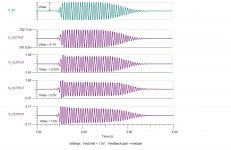
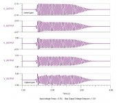
The attached plots show another set of tests I ran, very much like those shown above except that they were done with a 20Hz burst.
The distortion levels for the feedback gain are (from top to bottom) 10%, 0.65%, 0.44%, 1%, 1.1%. This is a very different profile than above. Even when pumping can be seen, the distortion is not high and only the amplitude is being modulated. It's important to realize that the amplitude modulation is not the same for all frequencies, because it is the low frequency boost that is being modulated by the circuit. The high frequency amplitude remains unchanged.
-Charlie
Attachments
Hi,
FWIW its not new, its a feature of most AV biased subs.
Its in some hifi subs, but they keep quiet about it.
rgds, sreten.
FWIW its not new, its a feature of most AV biased subs.
Its in some hifi subs, but they keep quiet about it.
rgds, sreten.
Wouldn't this be similar to what a Bag End ELF processor does, or am I mistaken
No, you are not mistaken... but I mentioned this in the opening post, including giving their Patent number on the technology.
They do it differently, and this way is "better" IMO because it uses a biquad filter not a double integrator to create the boost. This means that the response can extend up to whatever frequency you desire to operate the driver, e.g. not "just for subwoofers". It's also more flexible with the response shapes that can be accommodated.
-Charlie
Hi,
FWIW its not new, its a feature of most AV biased subs.
Its in some hifi subs, but they keep quiet about it.
rgds, sreten.
Why keep quiet about it?
- Status
- Not open for further replies.
- Home
- Loudspeakers
- Subwoofers
- LT with gain-dependent boost limiter - a new idea?