So what gauge magnet wire is on there now and what gauge would you suggest? I might have some left over from the tuner I made for my crystal radio 50 years ago.
Does anyone have a manufacture part # for the 2.2uf input caps and OPA2132 op amps?
I'm trying to place my order with mouser today. I already have all other parts in my cart just making sure I get the right parts.
Thanks in advance.
I'm trying to place my order with mouser today. I already have all other parts in my cart just making sure I get the right parts.
Thanks in advance.
My second mod was to remove the volume op-amp and almost all of the components around the op-amps, and wire the volume pot as a regular attenuator.
I removed R42 and R43 (to the right of the tone/direct switch, behind the treble pot) to disconnect the tone circuit from the switch, then wired the pot to the "tone" side of the switch. Now "tone" = on, "direct" = mute. I did it this way because in order to use the "direct" side of the switch, I would have had to remove the resistors under the switch, which were too hard to get to. I grounded the one end of the volume pot to the through-hole where the ground strap for the pot is connected.
This mod also improved clarity, and gave me more useful volume control range.
Red--
Which is the volume opamp and what things did you remove?
Thanks
CMoy?
Hey,
Red, Sofaspud, Bare.... even if people change the opamp in line with the volume, doesn't this still just end up an amp'd CMoy?
Hey,
Red, Sofaspud, Bare.... even if people change the opamp in line with the volume, doesn't this still just end up an amp'd CMoy?
I'm not sure I understand the question.
I swapped the stock 4558's with a couple SOIC LM833's I had on hand. When the volume was turned way up, where the distortion began getting extremely harsh to the ears, it seemed to improve the sound significantly. I don't have any measurements, and I'm not even certain of the input configuration, for my amp. But any improvement there is worth it IMO so I've no regrets about the mod.
Also IMO... the credit to Chu Moy is that he designed and web-published a great sounding, easy to build, readily modifiable portable DIY headphone amplifier project. Maybe more popular than he ever imagined it would be. So, his credit is well deserved, but I'm not prepared to call every op amp gain block a "CMoy."
So what gauge magnet wire is on there now and what gauge would you suggest? I might have some left over from the tuner I made for my crystal radio 50 years ago.
Simply does not matter the wire gauge ONLY the number of winds on it.
Mh value is derived from # of winds, Amp capability from the thickness /gauge of the wire used. Most any Electronics shop carries mag wire Or if seriously frugal; unwind a toy motor armature.
But it has to fit on fairly neatly.. so coathanger thick could be problematic 🙂
Hey,
Red, Sofaspud, Bare.... even if people change the opamp in line with the volume, doesn't this still just end up an amp'd CMoy?
What is a C'moy?
All I know is to remove 'at least' those junky opamps, on the right hand side of the board, as these remain partially in the circuit, unless physically removed
Does anyone have a manufacture part # for the 2.2uf input caps and OPA2132 op amps?
I'm trying to place my order with mouser today. I already have all other parts in my cart just making sure I get the right parts.
Thanks in advance.
OPA2132 IS the manufacturer's part number. As for 2.2uF caps, well that depends on what you want and how well you want it to fit the stock location. You could get electrolytics like what is already there, polyester, polypropylene, ceramic, etc etc. There are then numerous manufacturers of each of these types.
Red--
Which is the volume opamp and what things did you remove?
Thanks
U2 is the volume opamp I believe. Look at post 7 for a picture of all the stuff I removed.
You can safely remove all the components clustered around the opamps. But you'll need to rewire the input in some manner (with or without the volume control).
Last edited:
Oh no I was trying to change parts C42, I thought it was a 0.1uF cap... now that channel became a low-pass filter or high-pass filter.
Anyone know the correct capacitance for C42 and C43.
Just to check C31 and C30 are 2.2uF right?
Anyone know the correct capacitance for C42 and C43.
Just to check C31 and C30 are 2.2uF right?
If you bypass the volume op-amp (post #6 details keeping the volume control without the op-amp), you won't have to worry about C42 and C43 🙂
Sorry, I don't have a capacitance meter and it's not written on my boards.
Sorry, I don't have a capacitance meter and it's not written on my boards.
My multimeter can only be used on polarised caps 🙁 I will bypass it for the time being. I also bought a flip switch for bypassing, and also to switch back to use the op amps when I want to.
I love the op amp too. So I am going keep it there for now... I found a schematic of the old lepai board from the 2020 thread and there is a similar capacitor there which is of 33pF.
I am going to try change to that and see what happen, hope for the best.
I love the op amp too. So I am going keep it there for now... I found a schematic of the old lepai board from the 2020 thread and there is a similar capacitor there which is of 33pF.
I am going to try change to that and see what happen, hope for the best.
I'm not sure I understand the question.
I swapped the stock 4558's with a couple SOIC LM833's I had on hand. When the volume was turned way up, where the distortion began getting extremely harsh to the ears, it seemed to improve the sound significantly. I don't have any measurements, and I'm not even certain of the input configuration, for my amp. But any improvement there is worth it IMO so I've no regrets about the mod.
Also IMO... the credit to Chu Moy is that he designed and web-published a great sounding, easy to build, readily modifiable portable DIY headphone amplifier project. Maybe more popular than he ever imagined it would be. So, his credit is well deserved, but I'm not prepared to call every op amp gain block a "CMoy."
Sorry, but you are just amp'n his op amp design through a Tripath. Rebuttal?
Last edited:
His was a headphone amp design, not an op amp (circuit) design. I won't say it again.
Parry question: So what if it is "just amp'n his op amp design through a Tripath"?
Parry question: So what if it is "just amp'n his op amp design through a Tripath"?
hey guys, new here to the forums. i just received my 2020a+ from parts-express. will be using it to push pioneer bs-21 for my pc setup. the supplied power supply that i received is rated 12v 2a. would i be better off using something like this? (Amazon.com: 12v 6a Adapter Power Supply for LCD Monitor with Power Cord: Computers & Accessories) also, what are some of the popular mods that are done to these amps? i'm very much looking forward to modding this amp. thanks guys
Yes a 6A power supply would work better for your setup. I don't know if the one you linked has a plug that will fit, or whether it's centre positive or centre negative. Read through this thread, I detailed some of the common mods (replacing capacitors, inductors and removing/bypassing the opamps).
Hi guys, good to see people still playing with these. Anyway I might have damaged mine, not sure, thought I'd just post and see if anybody can help me.
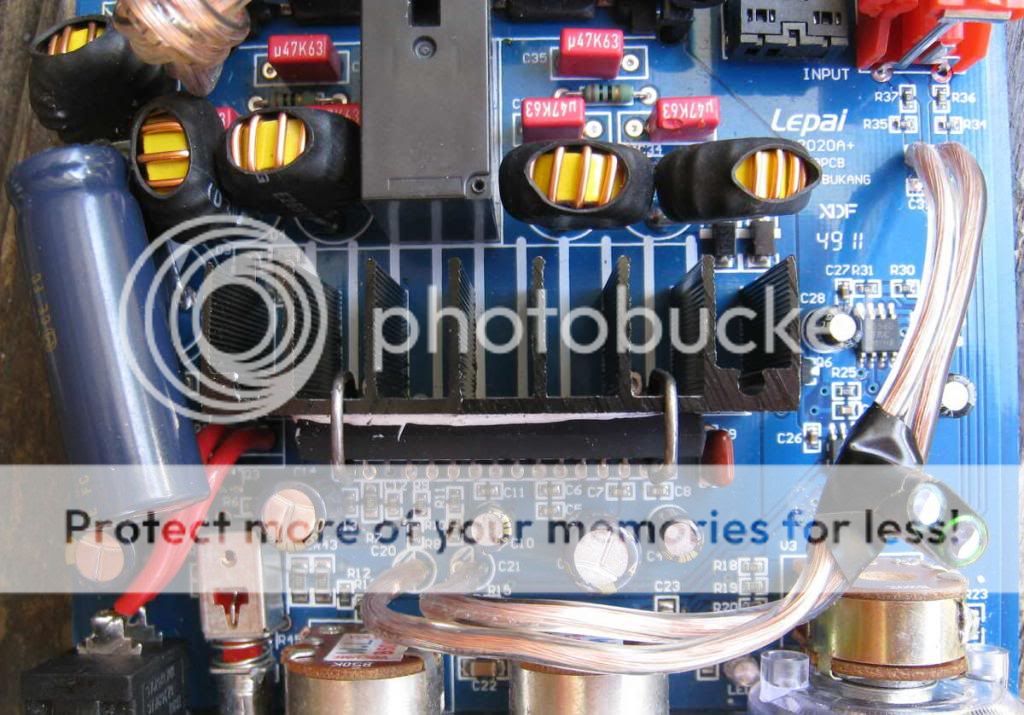
The problem is it does not put any sound out. LOL. But i think i know why, I did a few mods to mine as you can see in the pic. But what happened is, where I bypassed the O.P. amp stage, the 2 wires ended up touching each other just after they come away from the board near the RCA plugs. Anybody know if this could be a course for the TA2020 chip to fail? Or perhaps it can be reset? If anybody in the know could give there opinion i would be greatfull.
P.S. this picture is taken after a rewire.
Hi, I discovered this forum a while back and have been reading a lot of threads and saw all the discussion about modding the Lepai 2020A. I haven't done any diy amps or mods before. But this one looks like a perfect amp for what I am wanting to build.
I have a raspberry pi that I am wanting to use as a music player for in our bedroom. I already have the raspberry pi set up and running SqueezePlug and it works great. But I want to build a box to hold everything instead of a bunch of individual pieces that look ugly.
I drew up a little plan of what I am wanting to do and was hoping someone could point me in the direction of where to start with this, or if this is even going to work.
A few things I am wanting to accomplish.
1. One case for everything - Amp, RaspberryPi, Power Supply, DAC, USB Hub
2. Get rid of the cheap connectors and knobs on the amp and use good stuff.
3. Have the power supply built into the case so I can have 2 cord going to the wall. The power supply will need the 12V for the amp and 5v for the raspberry pi and usb hub
4. Have an Input Selector Knob to choose between 3.5mm aux, line in, and raspberry pi
5. Have Line Out -if possible
Here is the drawing I made.
Hopefully it makes since. I have a power switch in the front, but after thinking about it, I don't want it in the front. Instead I want a main power switch in the back and individual power switches for the raspberry pi and the amp.
I see that many of you have been bypassing the bass and treble controls. I may want to do that as well, but it might come in handy so for now I will plan to just relocate the knobs to the front panel of the box.
I plan to also replace the caps on the amp. I see a lot of people are replacing them differently than others. This is just for our bedroom. I am not needing crazy power out of this thing, but I do want good quality sound and the option to be able to crank it when I feel like it.
Most of this I doesn't seem to complicated to me, but the power supply is where I am totally lost. I don't know if I should be looking at a DIY psu, or what kind of psu I should buy.
The power switches, volume/tone control knobs and input selector are the other big ones.
Any advice/tips on how to go about this or even where to start looking would be great.
I have a raspberry pi that I am wanting to use as a music player for in our bedroom. I already have the raspberry pi set up and running SqueezePlug and it works great. But I want to build a box to hold everything instead of a bunch of individual pieces that look ugly.
I drew up a little plan of what I am wanting to do and was hoping someone could point me in the direction of where to start with this, or if this is even going to work.
A few things I am wanting to accomplish.
1. One case for everything - Amp, RaspberryPi, Power Supply, DAC, USB Hub
2. Get rid of the cheap connectors and knobs on the amp and use good stuff.
3. Have the power supply built into the case so I can have 2 cord going to the wall. The power supply will need the 12V for the amp and 5v for the raspberry pi and usb hub
4. Have an Input Selector Knob to choose between 3.5mm aux, line in, and raspberry pi
5. Have Line Out -if possible
Here is the drawing I made.
An externally hosted image should be here but it was not working when we last tested it.
Hopefully it makes since. I have a power switch in the front, but after thinking about it, I don't want it in the front. Instead I want a main power switch in the back and individual power switches for the raspberry pi and the amp.
I see that many of you have been bypassing the bass and treble controls. I may want to do that as well, but it might come in handy so for now I will plan to just relocate the knobs to the front panel of the box.
I plan to also replace the caps on the amp. I see a lot of people are replacing them differently than others. This is just for our bedroom. I am not needing crazy power out of this thing, but I do want good quality sound and the option to be able to crank it when I feel like it.
Most of this I doesn't seem to complicated to me, but the power supply is where I am totally lost. I don't know if I should be looking at a DIY psu, or what kind of psu I should buy.
The power switches, volume/tone control knobs and input selector are the other big ones.
Any advice/tips on how to go about this or even where to start looking would be great.
A good place to start if you want good quality sound: don't use the Raspberry Pi. The "analogue" output is class D just like the LP-2020A+, but it's done with software and is only capable of about 11 bits of resolution. I have one, connected to a pretty good amp, and it sounds like crap.
- Status
- Not open for further replies.
- Home
- Amplifiers
- Class D
- LP-2020A+ mod thread