Have you, by any chance, analyzed how supply decoupling specifically affects the performance of LM3886?
I have not analyzed it in detail, but I have noticed that the LM3886 tends to oscillate at output swings exceeding 30-32 Vp if you use less than the 10 uF of local bypass cap recommended in the data sheet. I have not found the exact limit, but a 10 uF X7R 50 V rated capacitor does not have enough capacitance at 35 V supply (due to its voltage coefficient) to ensure stable operation of the LM3886 with higher than ±28 V rails.
Your page on the topic starts with the assertion that if the supply to the LM3886 is bouncing, the LM3886 may behave in unintended ways, but you never give any design parameters.
I'm sure you can work backwards from the PSRR curves in the data sheet. Note that the PSRR is different for the two supplies. VEE has worse PSRR as the VAS is referenced to VEE.
You do mention, however, that no power supply non-idealities are included in the LM3886 model, and that the data sheet is ambiguous on the exact requirements for bypassing.
If I recall correctly, the data sheet is not ambiguous about the 470 uF minimum bulk cap on the board and the 100 nF local decoupling. There is also no ambiguity in the data sheet around the fact that a smaller electrolytic or tantalum cap is needed by the LM3886. The ambiguity arises around the exact value of that local smaller electrolytic/tantalum cap.
You can find the info in the application section in the data sheet.
although the version with one cap per rail works remarkably well.
Have you honestly tested it? I.e. run it at various supply voltages with both 4 Ω and 8 Ω load and watched the clipping behaviour on an oscilloscope?
In your view, how much decoupling is enough, and what specifically are the ill effects of various kinds of insufficient decoupling?
You'll need minimum 470 uF on each rail where the power enters the board. In addition, you need minimum 10 uF in parallel with 100 nF on each rail, located as close as possible to the LM3886. I normally use 1000 uF + 22 uF electrolytic + 1.0 uF X7R ceramic.
Tom
Last edited:
Thank you Tom, this is very helpful.
I did test my boards for clean clipping into 8ohm with an unregulated power supply giving about 31V rails at clipping, and they clipped fine with one 1500uF Panasonic FC per rail.
Out of curiosity, what other tests you'd run on your boards on top of what's in your specifications - i.e. in addition to the distortion, noise, and bandwidth?
Out of curiosity, what other tests you'd run on your boards on top of what's in your specifications - i.e. in addition to the distortion, noise, and bandwidth?
I tweak my measurement suite periodically, so the best way to keep track is to find my most recent project. In this case, the Modulus-686. You'll see THD, IMD, multi-tone IMD, noise floor, bandwidth, slew rate, etc.
In addition to what you see on my website, I measure the transient response with various capacitances in parallel with the 8 Ω load. I usually start at 1.0 nF and work my way up to 1.0 uF. I look at the ringing as function of load capacitance. I also look at how much capacitance it takes to make the amp unstable and compare that with the value I found in simulation as a sanity check.
On new designs I often measure the phase margin using a network analyzer. When I designed the HP-1, I used a 2 GHz spectrum analyzer to verify that the amp was stable. The LME49600 will happily oscillate in the FM radio band if you aren't careful. 🙂
Those are just the measurements I perform just before product launch. I'll often measure a whole range of stuff (internal nodes in the circuit, behaviour if one supply drops, etc.) during prototyping.
At the end of the design process - usually after updating my website and the design documentation, I rig the amp to a speaker, crack open a beer, and crank some tunes.
Tom
Last edited:
Thank you Tom for the comprehensive answers; I do appreciate your taking time and sharing your expertise.
May I ask you to touch another topic: the design process for the frequency compensation network for a composite amplifier like the Modulus? There are advocates for high loop gain amplifiers with high(er) order feedback networks here on the forum, and implementations besides the Modulus (two examples I've built in the past are the MyRef and the ZD-50), but I have not seen any reasonably detailed discussion of how to actually design one. Your products clearly show you know how to do it - may I ask you to shed some light?
May I ask you to touch another topic: the design process for the frequency compensation network for a composite amplifier like the Modulus? There are advocates for high loop gain amplifiers with high(er) order feedback networks here on the forum, and implementations besides the Modulus (two examples I've built in the past are the MyRef and the ZD-50), but I have not seen any reasonably detailed discussion of how to actually design one. Your products clearly show you know how to do it - may I ask you to shed some light?
In the Modulus-86, I use a combination of a few 1st order compensations (dominant pole, feedback lead/lag). It's nothing fancy, really. Just complicated. 🙂
The best treatment of the topic of compensation I've found is Chapter 8 of Franco. It's a lot more than I can cover here. Franco's writing is pretty accessible. He relies on a lot of graphical methods in his examples, which are far easier to follow than the raw equations.
The ISBN below is for the 3rd edition. The 2nd edition is just as good.
Tom
Franco: Sergio Franco: “Design with Operational Amplifiers and Analog Integrated Circuits”, McGraw-Hill, 2002, ISBN: 0-07-232084-2.
I'd like to add the seminal TI app note "FEEDBACK PLOTS DEFINE OP AMP AC PERFORMANCE" by Jerald G. Graeme (http://www.ti.com/lit/an/sboa015/sboa015.pdf).
While it doesn't detail much on how to implement compensation it explains what is the goal of compensation in the best way I've ever found. Of paramount importance is the line "Phase only matters at the interecept" which does away with the common misconception that the phase of the open-loop gain must never dip below 180° *anywhere* for stability (well, this is true for an "ultra general purpose" opamp that the user may run at any arbitrary noise gain but an audio amp always runs in a very resctricted range of noise gains).
While it doesn't detail much on how to implement compensation it explains what is the goal of compensation in the best way I've ever found. Of paramount importance is the line "Phase only matters at the interecept" which does away with the common misconception that the phase of the open-loop gain must never dip below 180° *anywhere* for stability (well, this is true for an "ultra general purpose" opamp that the user may run at any arbitrary noise gain but an audio amp always runs in a very resctricted range of noise gains).
Carter & Mancini, "Op Amps for Everyone", 5th edition (Op Amps for Everyone: Bruce Carter, Ron Mancini: 9780128116487: Books - Amazon.ca) has a lot of useful information as well.
The book is available from TI in .pdf form. For whatever reason, it does not show up in TI's search results, but you can find it pretty easily by searching for "op amps for everyone 5th edition pdf" using your favourite search engine.
Tom
The book is available from TI in .pdf form. For whatever reason, it does not show up in TI's search results, but you can find it pretty easily by searching for "op amps for everyone 5th edition pdf" using your favourite search engine.
Tom
Thank you gentlemen for the references!
I did hope there was a shortcut 😉 but digging into the next level of details should be interesting. The TI app note looks great and is very condensed, while the books will take some time to digest.
I did hope there was a shortcut 😉 but digging into the next level of details should be interesting. The TI app note looks great and is very condensed, while the books will take some time to digest.
Which is fine if you are sure that you will never get clipping.Of paramount importance is the line "Phase only matters at the interecept" which does away with the common misconception that the phase of the open-loop gain must never dip below 180° *anywhere* for stability
Thank you all for the recommended reading.
So far, I read the TI app note recommended by KSTR in post #46 above. I found it very compact and accessible.
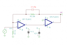
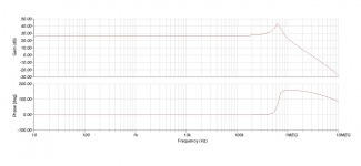
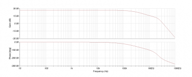
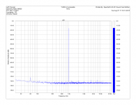
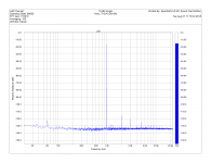
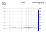
As an exercise, I designed, simulated, and built a composite amp with a gain of 21 with two halves of an TL082 - see attachments. As predicted, it oscillated without compensation, and properly compensated, it demonstrated very different distortion behavior compared to a single half of the TL082. The measurements below were taken at approx 8Vrms output level, just below clipping.
So far, I read the TI app note recommended by KSTR in post #46 above. I found it very compact and accessible.
As an exercise, I designed, simulated, and built a composite amp with a gain of 21 with two halves of an TL082 - see attachments. As predicted, it oscillated without compensation, and properly compensated, it demonstrated very different distortion behavior compared to a single half of the TL082. The measurements below were taken at approx 8Vrms output level, just below clipping.
Attachments
-
 TL082 composite sch.png5.7 KB · Views: 543
 -
 TL082 composite uncomp.png28.6 KB · Views: 531
 -
 TL082 composite comp.png23.2 KB · Views: 502
 -
 TL082 composite 1kHz.png49.9 KB · Views: 508
 -
 TL082 composite 19+20kHz.png50.7 KB · Views: 511
 -
 TL082 single 1kHz.png37.7 KB · Views: 265
 -
 TL082 single 19+20kHz.png50 KB · Views: 273
Last edited:
- Status
- Not open for further replies.
- Home
- Amplifiers
- Chip Amps
- Lower chipamp distortion through PCB routing