I want to introduce you one interesting circuit. There is absolutely nothing innovational, circuit is hyper simple. But, I hope, my experience of construction building will be helpful for novices.
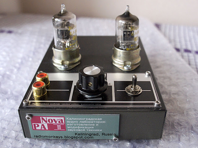
Tubes, used in this circuit may be 6AS6 or Russian 6Ж1П.
This tubes can work with LOW anode voltage!
In the circuit I suggest power is 12-20V DC
To use single supply, I put LM7806 voltage regulator to convert input DC to 6V for heat.
Original Article on my blog
This is very convenient because you don't need to build special power supply, you may use standard adapter (better is switching).
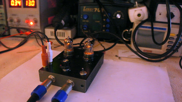
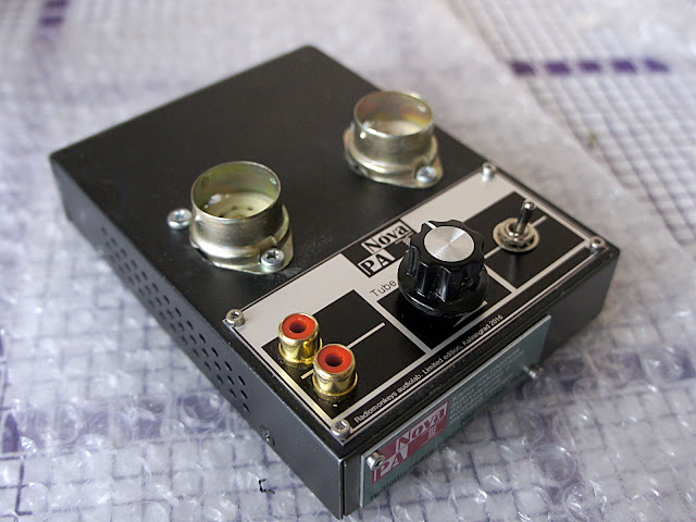
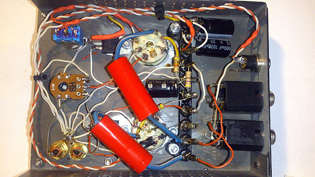
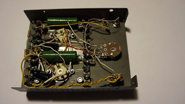
This was the first try. After testings, when I heared sound is really well (testing gear: Soundtech Series A mixing desc and Quested S6 monitors, signal sourse - audio interface e-mu tracker) I assembled the second version - with factory-made panels and whole better look.
Also, if anybody wants - there is video of testing.
And - certanly - inside mount.
or
Tubes, used in this circuit may be 6AS6 or Russian 6Ж1П.
This tubes can work with LOW anode voltage!
In the circuit I suggest power is 12-20V DC
To use single supply, I put LM7806 voltage regulator to convert input DC to 6V for heat.
Original Article on my blog
This is very convenient because you don't need to build special power supply, you may use standard adapter (better is switching).
This was the first try. After testings, when I heared sound is really well (testing gear: Soundtech Series A mixing desc and Quested S6 monitors, signal sourse - audio interface e-mu tracker) I assembled the second version - with factory-made panels and whole better look.
Also, if anybody wants - there is video of testing.
And - certanly - inside mount.
or
The Western equivalent is 6AK5 or EF95. 6AS6 has a different suppressor grid to give dual control characteristics.
You could wire the heaters in series and run from 12V to avoid the regulator.
This bias point is off the chart given in the 6AK5 datasheet, so estimating the likely anode distortion is not possible. Grid current distortion might be a problem too, unless the volume pot (and hence the source impedance) has a lowish value. Grid current will also eventually make the pot noisy; you should include a coupling capacitor and grid leak resistor to prevent this.
What was the aim of this circuit? In my opinion it is not a good example for novices to follow.
DF96 … “could wire heaters in series”
Actually, no. If you notice the curious connection of the sleeve of the heaters connected to +6 supply, this puts a –6 grid effective bias out there. While this whole arrangement might work for a ± 500 mV signal source … it really seems to have extraordinarily low inherent dynamic range.
CORRECTION: is that the cathode-sleeve, or an inverted representation of the heater coil? OH, I hate non-standard electronic symbols. They can be SO misleading!!!
As I've come to always do: if I'm designing a less-than–15-volt powered preamplifier or other audio device, our friends aren't tubes. They're those wonderful, now rather ancient JFETs. Warm, detailed, 3 volt or less bias. Basically high gain triodes without heaters. Some varieties edge toward lo-volt pentode curves. All are good.
GoatGuy
I think pin 2 is the cathode, although the little round blob is usually used for a cold cathode (at least in the West).
This circuit will have low gain (around 1?) but fairly high output impedance (~1k) so it isn't a preamp and it isn't a buffer. It might not add too much distortion if signal levels are kept low, but then it could add some noticeable noise. Hence my question about the aim.
This circuit will have low gain (around 1?) but fairly high output impedance (~1k) so it isn't a preamp and it isn't a buffer. It might not add too much distortion if signal levels are kept low, but then it could add some noticeable noise. Hence my question about the aim.
All your remarks are absolutely proper. But device works (see video).
About gain: I measured it, comparing on the oscilloscope input signal (source) amplitude and output. With anode resistor 1k gain is about 4-5. When I replaced 1k to 4.7k - gain became up to 10.
If you don't like to call this "preamplifier" - let it be "tube saturator" ^)
About gain: I measured it, comparing on the oscilloscope input signal (source) amplitude and output. With anode resistor 1k gain is about 4-5. When I replaced 1k to 4.7k - gain became up to 10.
If you don't like to call this "preamplifier" - let it be "tube saturator" ^)
I listened them with very good tract: mixer Soundtech Series A -> monitors Quested S6.
Sound got changed, but I can't say these are audible distortions.
Sound got changed, but I can't say these are audible distortions.
Can you show some oscillograms, to compare input and output signals, say, on 1 kHz, on a line level?
hmm... maybe later, because those one from the picture is sold (now travelling to UK 🙂 ), the second one is at my friend now...
Maybe I'd send device to You and You will test it by yourself? 🙂
Maybe I'd send device to You and You will test it by yourself? 🙂
The only two valves which cope reasonably well below 50V are the ECC88 (though grid current becomes the main issue here) and of course the rather excellent ECC86. Unfortunately the ECC86 went from been a cheap throw away valve to been an expensive valve when Broskie used it in one of his Akido amps.
The 24V ECC86 Aikido I would take over fairly much any expensive commercial offering.
Shoog
The 24V ECC86 Aikido I would take over fairly much any expensive commercial offering.
Shoog
Last edited:
wow... Do you think just one popular schematics affected for price-rating of one tube?
how about Russian analogue...
how about Russian analogue...
Yep, offer to the public a chance to build a good sounding valve preamp with none lethal voltages and you would be surprised at the impact on the popularity jump on an obscure little valve.
Its a great design incorporating a cascade and a cascode with a paltry B+ of 24V .
A lot of people follow Tubecad religiously.
Shoog
Its a great design incorporating a cascade and a cascode with a paltry B+ of 24V .
A lot of people follow Tubecad religiously.
Shoog
Maybe I'd send device to You and You will test it by yourself? 🙂
Thank you, I did a lot of laboratory works in TIASUR back in 70'Th, when designed synthesizers, guitar effects, and later, when designed and built Hig-End audio equipment. 😉
Trick number one: get specifications (Техническое Задание). I.e. what result you want to achieve. ;-)
Trick number two: select optimisation criteria (Критерии Оптимизации). ;-)
Trick number three: test, if the result met first 2 tricks. 🙂
Trick number two: select optimisation criteria (Критерии Оптимизации). ;-)
Trick number three: test, if the result met first 2 tricks. 🙂
I think that means that it distorted the sound, but in a way which the designer found pleasant.NovaPA said:Sound got changed, but I can't say these are audible distortions.
This is an excellent example of the sort of circuit which novices should avoid, unless their taste in distortion is similar to the designer.
- Home
- Amplifiers
- Tubes / Valves
- Low voltage tube line preamp