Hi Nova PA,
The schematic in ebay shows a 1 mega ohm resistor .Whereas the schema in post 1 has only 50 k linear pot.Any difference?
The schematic in ebay shows a 1 mega ohm resistor .Whereas the schema in post 1 has only 50 k linear pot.Any difference?
Hi,
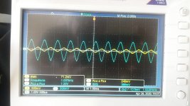
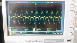
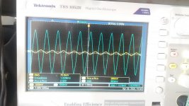
I made changes that had good results for 6sa6 / 5725w.
R3 / R5 from 1k to 47k. The gain for 12v is 5x and the gain for 30v is 10x.
Not bad for such a cheap tube.
I made changes that had good results for 6sa6 / 5725w.
R3 / R5 from 1k to 47k. The gain for 12v is 5x and the gain for 30v is 10x.
Not bad for such a cheap tube.
Attachments
Hi everybody,
I know it has been a while since anyone has posted on this thread but I was wanting to make this for my first tube project.
I have attempted to create my first PCB using this schematic for etching so it's more compact. (linked below)
To give some context the solder pads labeled L/R and then a number corresponding to the pins on a tube holder.
In the PCB id also run a wire with the 0.47uf capacitor from point A1 to B1. If anyone could tell me if this design is at all feasible that would be a big help.
And also should all the grounding run to the 3.5mm jack or the chassis. Thank you, Pascal.
Attachments
yes the schematic is here (I'm sorry for the confusing design it only makes sense to me)Can you just post a schematic? What's on the PDF doesn't tell us (well me anyway) much.
S.
basically, I've combined the two inputs into a dual gang pot and the large output capacitors will be placed from points A1 to B1 and A2 to B2 meaning a multi-layered PCB wasn't needed. And the different numbered solder pads with R or L will be wired to tube holders mounted on the chassis It's not a final design I just want to know if it would work at all. Thank you for your response, Pascal.
Last edited:
In my experience tubes operating at very low voltages, whether they be high voltage (200v to 300v) tubes operated at low voltages or low voltage tubes (e.g. 6GM8/ECC86) is that the sound lacks pace and drive compared to higher voltage tubes operating at higher voltages. As it's an anode follower the circuit shown will have a high output impedance and therefore be quite sensitive to cables and the power amp it is driving. One exception to low-ish voltage operation I can think of is Broskie's Aikido 12Vac running 6DJ8 tubes at around 80 volts. It can sound good and the voltages are non-scary. https://glass-ware.stores.yahoo.net/aikido12vac.html
S.
S.
Thank you for the recommendation I will definitely look into that as I hadn’t heard of the designs previously I think I’ll test this particular schematic on strip board as other people on the thread seem to think it’s a good sound. I’ll probably prototype it but I won’t commit to a full enclosure build. Pascal
Thank you for your additions to the schematic!Hi,
I made changes that had good results for 6sa6 / 5725w.
R3 / R5 from 1k to 47k. The gain for 12v is 5x and the gain for 30v is 10x.
Not bad for such a cheap tube.
I'm flattered by your interest in my design, and I apologize for the delayed response – for some reason, email notifications were turned off.Thank you for the recommendation I will definitely look into that as I hadn’t heard of the designs previously I think I’ll test this particular schematic on strip board as other people on the thread seem to think it’s a good sound. I’ll probably prototype it but I won’t commit to a full enclosure build. Pascal
If you're still interested in the design, let me know! I have ready-made PCBs available for it!

- Home
- Amplifiers
- Tubes / Valves
- Low voltage tube line preamp