This will be my first build using tubes of any sort. I just ordered two each off the lesser expensive end of the scale, I hope these will suit the purpose (I did request matched sections):
Electro-Harmonix 12AU7A / ECC82EH Additional Options: Matched Triodes (Balanced)
Tung-Sol 12AU7W / 6189 Additional Options: Matched Triodes (Balanced)
EDIT: Forgot to ask - Valery, which of the schematics would you recommend? There have been a few tweaks and mods and I'm not even sure which one Terry had success with in the end...
Jason, bearing in mind the issues Terry faces (still not clear for me), I would recommend to start with the latest option (Post #235) and then probably go few tweaks back.
I will also solder my second front-end PCB to gain more statistics at least "internally".
Maybe spoke too soon says the guy as he replaces two outputs and an predriver.
Ufff (((
I will solder my second channel and try more tubes today.
Mystery...
In my experiences the JJ au7a/ecc82eh tubes are markedly better sounding than the Electro Harmonix ..Cleaner brighter and yet sweeter sounds.
The electros are/were a disapointment
May or may not be similar in your circuits?
I use Electro Harmonix 12AU7EHG - gold plated pins option.
In this design (unlike in a purely tube-based amps), there is a relatively deep NFB, so individual differences are pretty much "smoothed" with it. However, this hybrid fully utilizes the tube benefits - low noise, high linearity, soft reaction on possible short term overloads. Sounds very nice. However, it would be still interesting to audition it with the tubes from other manufacturers...
I will have to do more testing today. It was my second board that blew the outputs. It was already built per the original layout and I had to go back through the thread to find the various changes and replace parts, make trace cuts, add jumpers, etc. I need to go over it with a fine tooth comb this morning and make sure I didn't miss anything. When I did the testing on the board that seemed a success, I didn't' have a load plugged into it. I realized that when testing the second board. One other thing that could have attributed to the damage is that I mistakenly switched the amp off and on again while I still had the dummy load attached. Thank God it wasn't a speaker and thank God I still had it running through the light bulb.. Still I can't be sure that didn't damage anything. More testing to come. Looks like before I do any testing with a speaker, I should include the protection circuit in the mix.
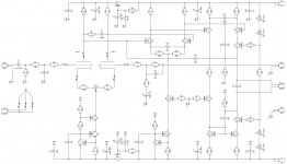
"As built" schematic
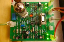
Hi All, just did some more research and testing with regards to providing stability during start-up and shut-down, when the tube may be not fully operational. C23 (6.8 pF) in position as shown provides firm behavior in all transition modes, also slightly increasing phase margin in normal operation. Orange cap on the right from the tube at the picture.
I have also put a 50 ohm trimmer between the input LTP cathodes - works fine, allowing fine-tuning the DC offset at the output. R35 on the schematic, blue multi-turn pot below the tube at the picture.
Running nicely for couple of days.
I love the way it sounds 😎
Jason, I recommend this one for your build.
Terry, I suppose, this one will be good for you as well, however, bearing in mind unexpected behavior of your build, please be careful.
Cheers,
Valery
Attachments
Last edited:
Excellent. My toobs arrived today. I have to get more parts for the OPS I will pair with them. What output devices are you using on the SlewMaster boards? Terry seems to have hit upon the fact his 'problem' OPS is stuffed with MJL21193/MJL21194 while his working ones use the faster MJL1302/MJL3281.
Hi Valery,
I added the cap. I only had 7p on hand hope that is good enough. I don't have any 50R pots so that will have to wait. I did get it to play some music but it is right on the edge. I only used it through the light bulb tester as I don't want to lose anymore output trannies. It will play fine as long as I don't push it. Get the volume up a little and the bias shoots up and the light bulb come on bright and stays there. It won't settle down until the amp is shut down and restarted. I'm closer but still don't feel safe enough to use it without the light bulb. I'll probably wait now for Jason to build his and see if he has similar problems of if his just works. He is a really good trouble shooter so I suspect his will work.
Blessings, Terry
Valery
Check this schematic , it is about of correct connection of tube filament with 6.3 VAC voltage from small tube heater transformer , and don`t forget that both LTP cathodes stays on relative high impedance , so parasitic capacitance between both cathodes and both filaments can introduce hum or some other unwanted effects .
All three secondary wires need to goes twisted up to amp board .
Best Regards !
Attachments

Excellent. My toobs arrived today. I have to get more parts for the OPS I will pair with them. What output devices are you using on the SlewMaster boards? Terry seems to have hit upon the fact his 'problem' OPS is stuffed with MJL21193/MJL21194 while his working ones use the faster MJL1302/MJL3281.
I actually used the slower ones (MJL21193/MJL21194) as well, however they showed no issues in my build. It appeared impossible to buy MJL1302/MJL3281 some easy way, so I ordered them from Mouser and it may take about a month for them o travel here. I will try them as well - it will be interesting to see the actual measurements.
See my simulation research here:
Modelling with different OP devices and the cure
So the slower ones are definitely less problematic, but the slower ones are also usable...
Cheers,
Valery
Hi Valery,
I added the cap. I only had 7p on hand hope that is good enough. I don't have any 50R pots so that will have to wait. I did get it to play some music but it is right on the edge. I only used it through the light bulb tester as I don't want to lose anymore output trannies. It will play fine as long as I don't push it. Get the volume up a little and the bias shoots up and the light bulb come on bright and stays there. It won't settle down until the amp is shut down and restarted. I'm closer but still don't feel safe enough to use it without the light bulb. I'll probably wait now for Jason to build his and see if he has similar problems of if his just works. He is a really good trouble shooter so I suspect his will work.
Blessings, Terry
Terry, did you use the slower OP option (the one with MJL21193/MJL21194)?
Increasing C107, C109 to 150pF (or even 220, but not more than 470) may help.
Cheers,
Valery
P.S. BTW, what drivers (Q107, Q108) do you use?
Valery
Check this schematic , it is about of correct connection of tube filament with 6.3 VAC voltage from small tube heater transformer , and don`t forget that both LTP cathodes stays on relative high impedance , so parasitic capacitance between both cathodes and both filaments can introduce hum or some other unwanted effects .
All three secondary wires need to goes twisted up to amp board .
Best Regards !
Hi Banat, thank you for recommendation - I've got no central contact at my transformer, so I use a fully "floating" heating supply with no issue.
I will keep this in mind though 😉
Cheers,
Valery
Hi Valery,
I didn't mean to suggest you use the 3281/1302. I only used them because I had a lot of them and could easily populate 4 boards and have replacements available if needed, which of course, they have. I'm looking forward to trying your fix with the cap change. I don't think On semi makes the MJL3281/1302 anymore. I have one more pair of boards and will try MJL4381/4302 in those and see how those work. I am also getting a pair of baby OPS from Jason and will probably go with the 4382/4302 in those as well. I may try the NJW0281/1302 for drivers instead of the MJW3281/1302 that I have been using. I'm not sure if those have played a role in my issues.
Blessings, Terry
Terry, did you use the slower OP option (the one with MJL21193/MJL21194)?
Increasing C107, C109 to 150pF (or even 220, but not more than 470) may help.
Cheers,
Valery
P.S. BTW, what drivers (Q107, Q108) do you use?
Hi, Valery,
Sorry, looks like we were typing at the same time. My last test were done using the boards with the MJL3281/1302 outputs. I hadn't used the boards with the 21193/94 outputs until yesterday when testing my new Symasiu IPS boards. The drivers I have been using for all six OPS I have built so far have been the MJW3281/1302 devices. I have a lot of them and hoped they would work well for these drivers. I'm not sure if they are a problem. If you think they are I can change them. I have a few other choices I could use there.
Thanks, Terry
Hi Valery,
I swapped in the 150p caps and that did the trick. Oscillation is gone in the OPS. Still a little leery about hooking up the hybrid without the light bulb. It is a 150 watt bub and shines bright if the amp is pushed at all. The problem is that once the lightbulb begins to shine, the rail voltage begins to drop. I'm wondering if that may be causing the tube to fall out. If that happens, would the offset jump again and cause the huge offset? I know this amp won't start up if I have a dummy load on the output.
Thanks, Terry
Hi Terry, when the light bulb shines bright - do you see oscillation at the oscilloscope hooked-up to the output? Depends on how much the drop is - at certain level down the tube may stop balancing the circuit - this is when the offset may increase.
What do you mean by "this amp won't start up if I have a dummy load on the output"?
Cheers,
Valery
What do you mean by "this amp won't start up if I have a dummy load on the output"?
Cheers,
Valery
Ah, I probably see what you mean - the load has to be connected to the output as soon as the offset is settled close to zero - that's right. The "plop" is rather significant here, especially if you don't heat-up the tube 20-30 seconds in advance - in this case the offset travels from rail to rail before settling and it's definitely better not to have the load connected at that time...
I haven't tried starting it up with the load connected and no lightbulb. With the light bulb in circuit, It will never start up. The load stops the voltage from settling, probably because the rails can't come up high enough. I'm afraid this amp might destroy a speaker if it were attached at startup. Speaker protection is a must with this setup. I worry a little if the speaker protection will work well enough if there is just a momentary disruption in power. If the so the delay in the speaker protection may be too quick. I'll have to test that.
Last edited:
Yes, start-up delay and speaker protection are a must here. I use a sophisticated micro-controller managed board for this purpose with appropriate algorithm and all timings set, as I mentioned earlier. It controls the start-up sequence (maintaining all delays, including the tube pre-heat) and checks if DC offset is acceptable before connecting the speaker.
Simple delay and protection circuit also may be used, as we discussed earlier - just test it a number of times, because the plop in the beginning will be higher than the one with my board in place.
Cheers,
Valery
Simple delay and protection circuit also may be used, as we discussed earlier - just test it a number of times, because the plop in the beginning will be higher than the one with my board in place.
Cheers,
Valery
Hi Valery
I received your boards from Terry today and I must say they are very nice indeed. The silkscreen is a little misaligned; nothing serious, and certainly won't detract from the enjoyment of of soldering.
Starting to collect all the parts now; namely, tubes, sockets, 6.3V transformer.
I received your boards from Terry today and I must say they are very nice indeed. The silkscreen is a little misaligned; nothing serious, and certainly won't detract from the enjoyment of of soldering.
Starting to collect all the parts now; namely, tubes, sockets, 6.3V transformer.
- Status
- Not open for further replies.
- Home
- Amplifiers
- Solid State
- Low TIM, low distortion hybrid front-end