I will definitely be looking into this tonight. I already ordered the parts for the crossover but what you posted sounds really promising and now I'm super curious how the plots will look.
After playing around with it some more, I will post what I end up doing. I may also install 2 sets of posts so that I can biamp the speaker later since having a flexible system is sounding more and more appealing to me.
After playing around with it some more, I will post what I end up doing. I may also install 2 sets of posts so that I can biamp the speaker later since having a flexible system is sounding more and more appealing to me.
Yeah I'm going to re-work the crossover. The 100uF doesn't make sense after drawing it out. It just becomes part of the second order filter and combines with the capacitance of the 47uF.
I think what may have happened is on Jeff Bagbys tool you can click to enter a zobel network (Cap+Res in Parallel with driver). When the values popped up for the cap and resistor, I incremented the resistor to 0 Ohms and I'm thinking this somehow caused a glitch in the spreadsheet where it failed to model the 47uF and 100uF in parallel (Thus combining the capacitance).
But yeah I agree now, the 100uF doesn't make any sense...
Also why does the impedance spike at around 30Hz not matter? Is it because it's extremely narrow given that we're working on a logarithmic scale? Do amplifiers have provisions to deal with the impedance spike (From resonances) since this is a common characteristic of woofers?
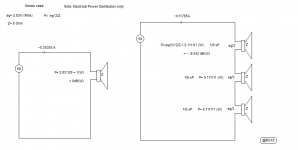
Just punched some calculations for the arrangement you posted. If each Dayton tweeter is punching 20 Watts... R1 will expend 55.17W (6.7Amps), R2 will expend 40.2693W (2.0375Amps), and R3 will expend 33.749W (4.7434 Amps).
For the series design, the 25 Ohm resistor will expend no more than 60W. BUT the impedance curve is not as nice... rising to just under 15Ohms at the high end and almost hitting 30 degrees in phase. Which trade-off makes more sense? Have the resistors in the parallel arrangement chew up power or throw the amplifier a more wonky impedance curve. Something tells me it might depend on the amp that is driving it.
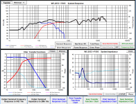
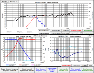
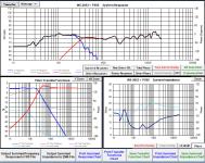
I'm really not sure which way to go here. The first plot below is of the arrangement Nanoloop described, I was unable to reflect the SPL drop in the full range that would result from adding a 1.5Ohm resistor in series however the impedance is accurately modeled (Hopefully that makes sense).
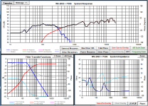
The second plot is a revised model of my previous crossover design (Back to the series arrangement with the 25 Ohm resistor in parallel with the full range drivers in series. The crossover (To clarify) is as follows:
LowPass:
-5mH
-147uF (This can be lowered to 47uF BUT the impedance plot gets thrown slightly more out-of-whack)
HighPass:
-47uF
-3.5mH
-25Ohm Paralleled with Full Range Drivers (Linked in Series)
Points to consider. The impedance curve on the PARALLEL arrangement is much smoother and nominal... hovering at around 4 Ohms. The crossover doesn't look as 'nice' and Im going to tweak it to see what I can do. When maxing out the PS95, there is a loss of 130 Watts across the resistors in total.
The SERIES arrangement sports a smoother crossover (At least in modeling) but employs a 147uF capacitor, has a loss of 60 Watts when maxing out the PS95 and has an impedance curve that rises to just under 15 Ohms at the higher frequencies. I appreciate the help so far as I'm really unsure what the best solution is here.
For the series design, the 25 Ohm resistor will expend no more than 60W. BUT the impedance curve is not as nice... rising to just under 15Ohms at the high end and almost hitting 30 degrees in phase. Which trade-off makes more sense? Have the resistors in the parallel arrangement chew up power or throw the amplifier a more wonky impedance curve. Something tells me it might depend on the amp that is driving it.
I'm really not sure which way to go here. The first plot below is of the arrangement Nanoloop described, I was unable to reflect the SPL drop in the full range that would result from adding a 1.5Ohm resistor in series however the impedance is accurately modeled (Hopefully that makes sense).
The second plot is a revised model of my previous crossover design (Back to the series arrangement with the 25 Ohm resistor in parallel with the full range drivers in series. The crossover (To clarify) is as follows:
LowPass:
-5mH
-147uF (This can be lowered to 47uF BUT the impedance plot gets thrown slightly more out-of-whack)
HighPass:
-47uF
-3.5mH
-25Ohm Paralleled with Full Range Drivers (Linked in Series)
Points to consider. The impedance curve on the PARALLEL arrangement is much smoother and nominal... hovering at around 4 Ohms. The crossover doesn't look as 'nice' and Im going to tweak it to see what I can do. When maxing out the PS95, there is a loss of 130 Watts across the resistors in total.
The SERIES arrangement sports a smoother crossover (At least in modeling) but employs a 147uF capacitor, has a loss of 60 Watts when maxing out the PS95 and has an impedance curve that rises to just under 15 Ohms at the higher frequencies. I appreciate the help so far as I'm really unsure what the best solution is here.
Attachments
Last edited:
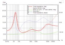
For reference here is an attached picture of the Modula MT (Designed by Jon Marsh) impedance plot. Based on my short conversations with Jon Marsh, I definitely feel his audio related judgement is on point. I notice that his impedance plot isnt too far off mine in terms of the behavior. Is there something I'm missing? He made these two statements regarding the impedance plot below.
""Here's the impedance curve- if your receiver can't drive this, it hasn't got a pulse..."
And this
"Last, the impedance curve. Pretty much anything should be able to drive this, except a crystal radio."
Learning a ton about impedance curves right now and how it's intertwined with crossover design. I find its really interesting looking at other loudspeaker build impedance plots but it can be difficult to distinguish what is good or poor behavior. Also I apologize for hijacking this thread! The build has a W5-2053 in it however... so I supposes it's related. I can take this somewhere else on the forum if this starts to get annoying 🙂
Attachments
... this means that each full range driver receives 1/3rd the power that it would have originally (Versus if there was only 1 full range driver).
Hi All,
FYI:
b🙂
Attachments
Thanks for the fix! Yeah I... that's going to affect my calculations. *Smacks head on table*
So the plot on the left is the new Series crossover plot. The plot on the right is the best parallel plot I could get.... Both crossovers use the same components (Im not limiting myself to that but I found the best response to be with the same components I ordered for the series crossover - so thats pretty cool). Im going to mess around more but bjorno's correction puts a damper on the series impedance design. Its starting to seem less realistic now.
So the plot on the left is the new Series crossover plot. The plot on the right is the best parallel plot I could get.... Both crossovers use the same components (Im not limiting myself to that but I found the best response to be with the same components I ordered for the series crossover - so thats pretty cool). Im going to mess around more but bjorno's correction puts a damper on the series impedance design. Its starting to seem less realistic now.
Attachments
Last edited:
Its a common characteristic and what reflex boxes usually try to do is tune the reflex port for the resonant peak. This splits the big peak into two very much smaller peaks either side of a valley where the big peak was. If you Google how to tune a reflex port you'll get a better, more complete and practical answer than my rather basic reply.Also why does the impedance spike at around 30Hz not matter? Is it because it's extremely narrow given that we're working on a logarithmic scale? Do amplifiers have provisions to deal with the impedance spike (From resonances) since this is a common characteristic of woofers?
5mH and 80uF on the Tang Band. Tune the port/drone cones to its resonant frequency. Drive it from the Sure amp. Done!
Your suggestion to fit separate speaker terminals for the woofer and mid-tweeters is absolutely the way to go. Its really easy to add a high pass and volume control BEFORE an amp that will let you fine adjust the blend between Tang Band and Daytons to suit the room, your tastes, the music, etc.
If you go parallel then another option is to add a series R for each Dayton so when wired in parallel, you achieve a nominal 4R. I think a 4R 10W resistor for each would do. It makes each Dayton 12R, roughly. Then put the 80uF 5mH high pass and you'd have a decent crossover with only the efficiency mismatch to resolve.
I have no idea what that mismatch will be though. I would build this and run it from one amp, using equalization to work out what I needed. Each Dayton is 85 and Tang Band is 80 so of course,at least -5dB, maybe as much as -11dB. Dunno. The 4R in series would be about 2.5dB of that.
Last edited:
Looks like I'm going with to purchase a MiniDsp. I dropped enough money on materials that it would be too foolish to try and nail this crossover down with no tuning (I would tune it, but you have to work within finite component restrictions) so I will be doing some DSP work it seems.
The efficiency mismatch is pretty brutal... I think I need to drop almost 11dB and I'm realizing that it's just more efficient to do this all prior to amping rather than waste the energy
The efficiency mismatch is pretty brutal... I think I need to drop almost 11dB and I'm realizing that it's just more efficient to do this all prior to amping rather than waste the energy
Anyone recommend anything other than MiniDsp? That's a good digital solution, should I pursue an active analog solution? I plan on going with two monoprice, 120W Mixer Amps (no logo) since I won't need to purchase a 12V supply to run the sure amp (Just trying to make it easier so I can focus on testing).
Bi-amping is the best way but I think you're going the wrong way with a mini dsp just for this speaker because you are not going to get an ideal crossover no matter what you do and that's because you're using 3 full range drivers to disperse a full range of sound evenly over 360. Look at the off axis treble response of the drivers - can they do 120degrees? So the sound will be warm, bright, warm, bright and warm, then bright, as you move around the speaker. I think you need to build it, listen to it and then consider if you want to spend more on it or go for a markII version. If you haven't yet ordered the wood, how about making it a 180 speaker instead of 360?
Last edited:
I feel like the MiniDsp would be a good option because of the on the fly adjustments. Is there an alternative method that you are referring to / equipment that makes more sense?
Yes, I think I'm going to have to play around with the arrangement... my hope was that their acoustic centers are close enough together that at two feet away the sound waves would combine into a relative 'ring'. Close field listening (Less than five feet) won't sound great if walking by
Yes, I think I'm going to have to play around with the arrangement... my hope was that their acoustic centers are close enough together that at two feet away the sound waves would combine into a relative 'ring'. Close field listening (Less than five feet) won't sound great if walking by
With the MiniDsp shouldn't I be able to achieve crossovers that can't easily be constructed due to it being digital?
The speaker is being 3D printed in a Wood / PLA combination. I have it sliced up into pieces so that a large 3D printer can handle it. The base is printing tonight as we speak.
The speaker is being 3D printed in a Wood / PLA combination. I have it sliced up into pieces so that a large 3D printer can handle it. The base is printing tonight as we speak.
My concern with the mini dsp is that you are spending a lot on a speaker for the level of performance it will offer. The crossover might be the least of the issues that are noticeable. Also, I've seen some comments that their analogue in-out devices don't sound so good and from the descriptions, I guess they didn't pay enough attention to jitter. However, as a tool to discover what needs to change and by how much, I don't think it can be beat when used with a decent mic.
My assumption has been that the room, its reflections, and its acoustic nodes and peaks will dominate the further you move away from the speaker. This will boost/cut the subjective bass making the sound thin/fat. Combined with a lack of treble dispersion, you may hear extremely thin/fat sound. Three synchronised drivers firing in different directions will cause a lot of delayed reflections meeting at any given point in the room. I can't imagine how this will sound good, but perhaps it won't be objectionable for a mono speaker. When I've looked at 360 speakers, they seem to have the drivers firing at a surface that reflects the sound into the room, not firing directly into the room. Full range drivers don't, in my experience, tend to disperse treble - they tend to beam it, creating treble hot spots - quite the opposite of what you seem to hope for. So, frankly, I have no idea how it will sound and that makes me glad it's your money, not mine. ;-)
If the panels are on the way, time to build it and see eh? BTW I'm delighted you are doing this - it is a very interesting project. I really hope it rocks. 🙂
Last edited:
At work right now so will type up a lengthier reply tonight... what program is that? Wish I had known about it during my driver selection!! (I should have done more research). So early in the design process I switched from the Dayton RS75 to the PS95... happy I did as im sure the RS75 would perform worse in the above analysis.
I wonder if there is a 'better' driver for this application? Also the drivers are closer together than the array above (Albeit it's pretty close) I wonder if this would improve or worsen results. I hope that program is free. I would love to play around with it tonight.
My crossover I believe will be around 250Hz. Really only employing the Tang Band for the really low frequencies
At work right now so will type up a lengthier reply tonight... what program is that? Wish I had known about it during my driver selection!! (I should have done more research). So early in the design process I switched from the Dayton RS75 to the PS95... happy I did as im sure the RS75 would perform worse in the above analysis.
I wonder if there is a 'better' driver for this application? Also the drivers are closer together than the array above (Albeit it's pretty close) I wonder if this would improve or worsen results. I hope that program is free. I would love to play around with it tonight.
My crossover I believe will be around 250Hz. Really only employing the Tang Band for the really low frequencies
Hi WaveCarver,
OK to XO at 250 Hz provided the mean C-C from 3 x PS95 to the Sub Driver is around a ft or less.
You can easily adapt the Plots(Driver C-C= 17.1 cm) to your actual Diver C-C Distance by multiplying the Plot frequency with C-C old/ C-C new.
Minimal C-C is returns best summed FR but I think it becomes a Moth point for a Mono Speaker when the mean vertical C-C Distance is less than Lambda/2(I prefer <=Lambda/4 as a limit) at the XO frequency.
If your measure of the actual C-C is e.g. 13.68 cm, then the Plot for 2000Hz is valid for the 2500Hz Plot as 2000 x 17.1/13.68 = 1.25 x 2000= 2500Hz.
I only use Trade of Tool Programs when Posting Here at diyAudio thus the Arrayshow.exe is a free Program to download.
Note: Will only open in WinXP or older. I use Oracle VM VirtualBox when in Windows 10.
CareySound Software ::
You can also search for more information: ArraySHOW from Mark Ureda and EVI Audio
Low-Frequency Directivity and Arrays
b 🙂
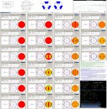
PS: If you need a Mono configuration with very small Dispersion error: See my (Bessel) 12ringarray81mm.gif using 3” Drivers, here a Wall Mount Layout that at Distances above 1.5 ft provides Omni dispersion but of course only limited by the choice of Drivers.
Attachments
Awesome stuff bjorno - it seems mono is the key 🙂 Which 3" drivers did you use? My belief is that a 3" coaxial will work better than a 3" full range for dispersion. Have you ever modelled that? Just curious since there are some available.

Last edited:
Hello
I am going to use this subwoofer W5-2053 with a Tang Bang passive radiator - PR10-A - 5" Subwoofer Bundle
My project is to create small (3-6L) subwoofer with passive radiator (my topic is here Small (3-6 L) passive radiator subwoofer design )
But I am wondering about W5-2053 because on the parts express site there are some comments that this subwoofer should not be overloaded (the coil heats up) and it's not particularly loud. Is it so? someone had problems with this?
And by the way, is there enough amplifier (sure JAB3 50W RMS) for this subwoofer I need more powerful one?
Tang Bang says that nominal power of W5-2053 is 40 Watts
- Status
- Not open for further replies.
- Home
- Loudspeakers
- Subwoofers
- Low THD Tang Band RBM drivers?