PS my hands are pretty small 😀
xmmmmm my hands are pretty small ..... so is your proximity in your ground frame ...pretty small....
You might have a look at this one: The β22 Stereo Amplifier
An headphones amp at first which is also able to produce around 18W/8R (maximum) with the proper power supply.
An headphones amp at first which is also able to produce around 18W/8R (maximum) with the proper power supply.
I've been using this for the past three years or so.
Hasn't exploded yet. No protection (current limiting transistors can be added easily). Sounds fine. Comes out of saturation quite quickly, which is nice.
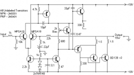
The "4-0976" are housemarked transistors which were driving solenoids (think dot matrix printer). They should be around 100V, 3A, something like a TIP31. TIP31 will work fine as a substitute, and you could also add the complement for a proper darlington output stage instead of the quasi-complementary circuit, if you were so inclined.
Ironically, I have a printed circuit board for this, however, it was hand drawn, so I don't have an electronic copy. 😛
Tim
An externally hosted image should be here but it was not working when we last tested it.
Hasn't exploded yet. No protection (current limiting transistors can be added easily). Sounds fine. Comes out of saturation quite quickly, which is nice.
The "4-0976" are housemarked transistors which were driving solenoids (think dot matrix printer). They should be around 100V, 3A, something like a TIP31. TIP31 will work fine as a substitute, and you could also add the complement for a proper darlington output stage instead of the quasi-complementary circuit, if you were so inclined.
Ironically, I have a printed circuit board for this, however, it was hand drawn, so I don't have an electronic copy. 😛
Tim
Last edited:
Thanks for all the replies and suggestions!
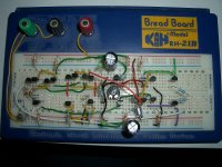
I have been trying to get the Diamante design working, firstly in its normal configuration but then with the aim to get it driving speakers. Unfortunately, my breadboarded effort (attached) has about -1V offset and I'm at a loss for seeing an error. I did have a transistor in upside-down at first, which caused 11V or so offset, I had wondered if surrounding ones had been damaged due to this error but having replaced them I got the same result. I still want to persue the design as it seems it has the potential to be very high performance.
Thanks Miles Prower for the schematic, it's another design I will consider though I don't currently have the specified outputs. I have loads of BD139 though if they can be used!
00940, another high performance design it appears. It looks very good, Not sure I could get it to work on stripboard and some of those devices might be a bit costly, but I'll keep it in mind.
h_a, this sounds interesting, I'd have to do a lot of research though to get the details to build one.
Sch3mat1c, a nice and simple design, simple enough for me to try out, assuming it can be tested with 2N5551 and 2N5401 transistors and BD139 output devices? I may have a pair of TIP31s though, but one's a TIP31A and one's a TIP31C, probably not an issue but I do have lots of BD139 so it'd be nice to use them! If required, how would I use 2 pairs of BD139 outputs? I also have loads of MPSA18, but no complimentary devices. Any idea of the performance of this amplifier?
Attachments
late input
Dr.em
Maybe you could check Erik Margan's idea,I built simplified(slightly)versions about20 years ago and still love 'em
Regards Albin
ps I used tip127 and comp as outputs
Dr.em
Maybe you could check Erik Margan's idea,I built simplified(slightly)versions about20 years ago and still love 'em
Regards Albin
ps I used tip127 and comp as outputs
Last edited:
Sch3mat1c, a nice and simple design, simple enough for me to try out, assuming it can be tested with 2N5551 and 2N5401 transistors and BD139 output devices? I may have a pair of TIP31s though, but one's a TIP31A and one's a TIP31C, probably not an issue but I do have lots of BD139 so it'd be nice to use them! If required, how would I use 2 pairs of BD139 outputs? I also have loads of MPSA18, but no complimentary devices. Any idea of the performance of this amplifier?
SS amps are very noncritical, only the differential pair should really be matched. 2N5551 and 5401 will do fine. BD139 is rather small (12.5W max.) but will do a fine job if you keep the current down (16 ohm speakers, settle for <5W output?). Otherwise, you can connect several in parallel, adding seperate emitter resistors for each.
Open loop DC gain is around 60dB, bandwidth ends around 100kHz, slew rate something like 10V/us, etc. Overall a very average discrete SSamp.
Tim
Thanks Miles Prower for the schematic, it's another design I will consider though I don't currently have the specified outputs. I have loads of BD139 though if they can be used!
I can't absolutely guarantee that those BD139s will work, however, I don't believe that making that substitution won't work. They may be a bit low on the hfe, but not by much. Since these finals have a higher Pc rating, they should be less likely to poof on overdrive, although this has not been a problem since I've been running these speaker boxes for five years now without any incidents.
If you do go that route, I would definitely suggest including the overdrive detector, or making sure that you keep your sound card output low enough to avoid overdrive, otherwise poofed speeks is definitely a possibility.
stripped back
A headphone amp design as Kevin Gilmore's K1000 challenger is easy enough to downsize to 5-15W in Class AB.
Attachments

Last edited:
Thanks for the further suggestions!
Sch3mat1c, I've breadboarded your amp and will test it (currently only 1 pair of BD139). Can you suggest a bias current (mv accross 1ohm resistor) and which way should I set the wiper initially?
Would 3 pairs of output BD139s be ok? Or will that be too much base capacitance to drive or something? I should use two 1ohm resistors per pair, how many watts should these resistors be rated at? I'd like to keep them small.
Member
Joined 2009
Paid Member
I would suggest going to look at what the 'headphone amp guys' are doing. They are often building simple low power circuits and some of them favour discrete designs. Several of them will have been built and listened to, problems identified and solved etc. so most likely a good source of information.
Probably a good idea yeah, the Diamante idea was along those lines but I haven't got it working yet. I'm keeping the breadboarded one though in case I figure it out.
In fact, I'm testing Sch3mat1c's design and am having essentially the same issue! I managed to set the bias (guessed it at 10mv accross each 1.2R) no problem, but have an offset voltage, this time of 1.7V positive. No unusual noise shows on the scope. What would be a common cause of this, that's surely far too much to simply be from not matching transistors?
EDIT: hadn't connected the right hand input transistor's collector to +V 😱 . Now 25mv, ok but can be improved with matching I'm sure. On to real testing 🙂
Last edited:
Well, it's working quite well. Pulling ~30ma per rail idle, about right for bias current? It's dead quiet into speakers, no hiss or hum, which is certainly nice. Turn on pop is minimal too, which is also desirable since it'll be powering mini speakers. It is running from a regulated test supply currently though, should I expect more noise with an unregulated supply? How is the PSRR?
I hear some small amount of distortion with sine test tones, but then I'm using a small speaker free air to test so it could be the driver? If anyone could confirm this is enough bias current that'd be great. Still on one pair of BD139, I'll have to try adding another once I've prepared the heatsink for them (half an old CPU cooler). It stays completely cool btw 😎
I hear some small amount of distortion with sine test tones, but then I'm using a small speaker free air to test so it could be the driver? If anyone could confirm this is enough bias current that'd be great. Still on one pair of BD139, I'll have to try adding another once I've prepared the heatsink for them (half an old CPU cooler). It stays completely cool btw 😎
Thanks for the further suggestions!
Sch3mat1c, I've breadboarded your amp and will test it (currently only 1 pair of BD139). Can you suggest a bias current (mv accross 1ohm resistor) and which way should I set the wiper initially?
Would 3 pairs of output BD139s be ok? Or will that be too much base capacitance to drive or something? I should use two 1ohm resistors per pair, how many watts should these resistors be rated at? I'd like to keep them small.
Set the trimmer towards the top, so the Vbe multiplier is set to the minimum voltage (about 0.7V). This will set class C initially.
20mA = 20mV per resistor is a fine starting point. It only needs to be biased into conduction; how far doesn't matter, except that more class A = more power dissipation = more prone to thermal runaway.
2-3 pairs of BD139 would be okay. If using 3 per side, more resistance, perhaps 2.2 ohms per emitter, would be better.
This is getting a little more complicated, so I should draw it...
An externally hosted image should be here but it was not working when we last tested it.
I moved a few other things around for clarity, and changed the feedback resistor to 22k for more gain. The old gain of 10 is a little low; 20 as shown should be just right for most purposes.
Tim
Well, it's working quite well. Pulling ~30ma per rail idle, about right for bias current? It's dead quiet into speakers, no hiss or hum, which is certainly nice. Turn on pop is minimal too, which is also desirable since it'll be powering mini speakers. It is running from a regulated test supply currently though, should I expect more noise with an unregulated supply? How is the PSRR?
I hear some small amount of distortion with sine test tones, but then I'm using a small speaker free air to test so it could be the driver? If anyone could confirm this is enough bias current that'd be great. Still on one pair of BD139, I'll have to try adding another once I've prepared the heatsink for them (half an old CPU cooler). It stays completely cool btw 😎
How much voltage? If as rated, then 30mA * 18V = 0.5W, enough to get those transistors pretty toasty without a heatsink, but not very noticable if you've got a good sized one.
Come to think of it, as much as 100mA would be fine. That's 1.8W per side, or 0.6W per transistor (once you get all three pairs in). As long as it's more than a few mA, and not so much that it burns up, it's fine.
FYI, you should probably build this on ground plane or something... even with emitter resistors, I've had paralleled BJTs play badly together without any apparent reason. Have you checked for parasitic oscillation or squegging yet? I found the 33pF B-C capacitor necessary to keep the darlington stable, YMMV.
The prototype model has an ordinary iron power supply, so at idle there will be a little supply ripple. I don't hear anything. On the scope (i.e., if I can't see it, there's less than 5% of it), PSRR only shows up in clipping, which you'd expect.
The turn-on-pop resistance is quite nice, I noticed that too. I guess bias settles quickly. The turn-on pop itself is minimal, and I think most of the noise I hear comes from the power switch (i.e., RFI), rather than PSRR directly.
Tim
Hi Sch3,
why quasi complementary?
Why a ground plane?
Why the extra 1r0 for measuring the output bias?
why quasi complementary?
Why a ground plane?
Why the extra 1r0 for measuring the output bias?
Thanks for the re-draw!
A little concerned at the mention of a ground plane, I fully intend to build this on stripboard, though I guess it'll be mounted over a grounded aluminium box. The single output pair version is working fine on breadboard/plugblock, no oscillations on scope, clean looking sine output. I guess I'll need to see how 2 pairs get on. If that causes trouble, I guess I'll have to invest in larger transistors and stick to a single pair, which would be a shame. I'm thinking 2 pairs will be sufficient though, so mabye 1.5r in each lead? I'll have to use 1.2r to test though, all I have. Are the 1r resistors after these not required then? Are 1W metal film resistors sufficient here in the long term?
I'm using ceramics for the small capacitors on this breadboard version, they are all I have. Is it ok to remove the 18pF capacitor in the feedback loop? Not sure if I'll want to increase the gain too much in this application, I'll have to check how it gets on with the output from a PC and a 10K pot at the input. I suppose I need a capacitor to couple the pot's wiper to the input of this amplifier?
I could go for a complimentary pair, I have a few BD140s too, if there is any advantage to doing this?
I'll be trying out replacing the input stage with a pair of MPSA18s. I have about 90 so I should be able to match them quite well from these.
remember to match using the same Vbe and the same operational Ic for the devices while holding Vce, Pq, Tc, Tj, at equal values during the testing/matching.I should be able to match them quite well from these.
You will achieve little by comparing hFE using a transistor hFE function integrated into a DMM.
You will achieve little by comparing Ic & hFE if you do not hold Vbe at a known constant voltage.
If you let the device temperature change all your results are wasted.
That sounds quite in-depth! I remember matching the transistors in my Symasym amplifiers just using a DMM, with hFE test and the diode tester for Vbe. The offset voltages are all below 3mv, I checked one recently as it had been out of service for a while and it was literally 0mv! It did drift to 1 or 2mv after a while though. I'll see how I get on, I certainly remember I think Vbe drifting a lot with finger heat, I had to let them sit for a while to get useable values.
I started to re-draw the schematic with complemantary pairs, but got confused about some of it 😱. It is rather similar to Rod Elliots P3A actually if configured as a complimentary output stage.
I started to re-draw the schematic with complemantary pairs, but got confused about some of it 😱. It is rather similar to Rod Elliots P3A actually if configured as a complimentary output stage.
Attachments
The seperate emitter resistors are *required* to ensure matching of the paralleled transistors. As shown, you have seperate *collector* resistors, which completely defeats the purpose. The common 1 ohm is still required, at least on the bottom side, so the PNP driver transistor knows how much current is flowing on its side.
Complementary (complimentary, notice the "I", means a good comment 🙂 ) would look like this:
http://myweb.msoe.edu/williamstm/Images/Quasi_With_Comp.png
Tim
Complementary (complimentary, notice the "I", means a good comment 🙂 ) would look like this:
http://myweb.msoe.edu/williamstm/Images/Quasi_With_Comp.png
Tim
- Status
- Not open for further replies.
- Home
- Amplifiers
- Solid State
- Low power discrete designs?