Good point. I would like to match the noise/hum performance of a Denon PMA-1500, which is silent enough not to add any hiss by itself (specs say 108 dB SNR) and be better than the DSP, which has 105 dB SNR.
You have up to 3V out of your DSP. You need 4V to make 2W in 8r.
So gain should be barely above unity.
How do you feel about heat? Push-pull or choke-loaded A is 50% efficient, CCS-loaded is 25%, resistor-loaded is 8%. So for 2W out this leads to 4W, 8W, or 24W dissipation. (Allow another 20% for losses and bias.)
The 24W competes with a 5W SE tube amp, but in Silicon will be quite large heatsinks and resistors. (We can't run a heatsink as hot as a tube, and we don't like resistors too very hot.)
An inexpensive 24V 40VA (1.6A) furnace transformer may be an adequate choke, especially for mid-high audio band. It's not made for DC, but worked well below rating and not aiming for 40Hz, it may be fine.
Let’s not reinvent the wheel. Just go with a MOFO and microwave oven transformer. It’s all worked out in this thread.
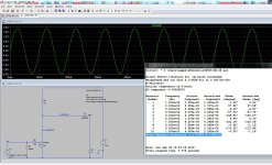
Build This MoFo!
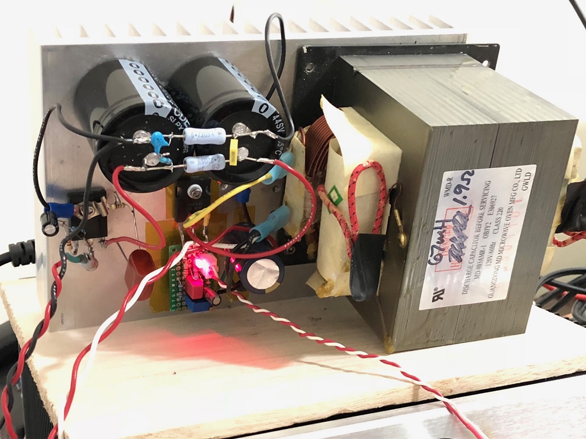
Superb harmonic profile:
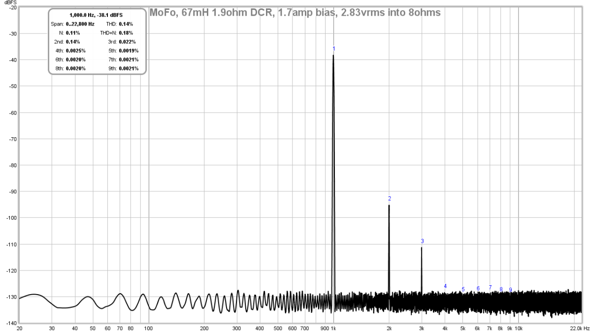
With a 24v 5A SMPS you can get about 11w rms. Will need a preamp with lots of swing though.
But 2w is something in the realm of maybe a headphone amplifier output from your sound interface.
Build This MoFo!
Superb harmonic profile:
With a 24v 5A SMPS you can get about 11w rms. Will need a preamp with lots of swing though.
But 2w is something in the realm of maybe a headphone amplifier output from your sound interface.
I can live with 20% efficiency, when the maximum requested power is 2 W per channel.
The MoFo is on my list of things to try out. It looks like it could work even without gain, at least for the trial
The MoFo is on my list of things to try out. It looks like it could work even without gain, at least for the trial
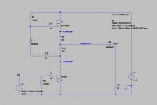
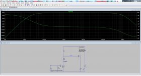
A simple powerbuffer with low distortion and very low noise due to the lack of voltage gain. Can be powered from a cheap 13,8 volt 150 watt Meanwell SMPS.
I would add a 1 mH air core coil and a 10000 mF filtering capacitor to each channel to lower the switching noise from the SMPS.
C1 and C2 does not need to be that large in real life. If you are using the amp to drive a high frequency compression driver then C2 can be 22 - 47 mF or so.
I would use at least a 1000 mF capacitor for C1.
Attachments
Last edited:
Now there are some options to choose from. Using a SMPS with filtering will reduce weight, my lab supply is over 10 kg🙂
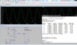
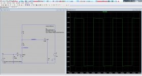
With a simple power resistor instead of the SRPP modulated current source you get more distortion and less voltage swing, but the amp is very cheap and easy to build with point to point soldering of the components. R1 can be a TO-247 thin film 100 watt power resistor.
The slightly increased THD is mostly a positive going second harmonic making the amp sound more like a nice tube amp with a more forward and vivid presentation of music.
The slightly increased THD is mostly a positive going second harmonic making the amp sound more like a nice tube amp with a more forward and vivid presentation of music.
Attachments
Since my power requirements are low, I decided to try a follower powered from 12 V. It will work with a 5 mH inductor or a resistor and a relatively small heat sink.
What gain stage would be recommended when I will need more Watts?
What gain stage would be recommended when I will need more Watts?
Nice little circuit, but it would have to be modified to single supply and capacitor coupling - because then I do not need an external capacitor to protect the compression drivers.
Nice little circuit, but it would have to be modified to single supply and capacitor coupling....
So you need it drawn-out for you?
Attachments
Thanks a lot! I was actually going to try to redraw it and simulate in MicroCap. You save at least one hour for me🙂 So this one definitely goes on the list of things to try out.
Gain stage ...
a small BjT, hFE > 100, two resistors or a trimmer, and two coupling caps.
And a little condenser parallel "feedback", may be.
If V/out is the same as V/in of the follower, you will need just one coupling-cap.
But, better would be, to build an power-amp than a follower AND a pre-amp.
An other good pre-follower-solution:
Project 83 - MOSFET Power Follower
cumbb, I meant that the gain stage would be inside the same box and powered from the same supply as the follower.
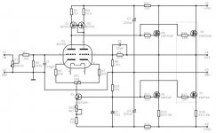
Actually I built this hybrid ECC88 (for gain) + Mosfet Follower amplifier a long time ago (as a school project, designing the PCB and building a prototype), I need to dig it out, it never made it to a final product - especially due to the crazy cooling and power supply requirements.
Actually I built this hybrid ECC88 (for gain) + Mosfet Follower amplifier a long time ago (as a school project, designing the PCB and building a prototype), I need to dig it out, it never made it to a final product - especially due to the crazy cooling and power supply requirements.
Attachments
I meant too;-)
The school project is too complex to get a clean tone, sound. And never a complementary-transes-pp and not "complementary-psu's". My mind.
A valve for gain is a good idea.
You could use an ECC182, 13P1S, ECC86, EF98 ... driven by 12 Volt.
Should be possible.
The school project is too complex to get a clean tone, sound. And never a complementary-transes-pp and not "complementary-psu's". My mind.
A valve for gain is a good idea.
You could use an ECC182, 13P1S, ECC86, EF98 ... driven by 12 Volt.
Should be possible.
- Home
- Amplifiers
- Solid State
- Low power 2 W @ 8 ohm, 4 - 16 ohm usable simple, class A SE - any recommendations?