...But the buffer implies reclocking, by definition. Reclocking is where the jitter would be removed, or if badly done, introduced. Bad reclocking is highly unlikely...But again, since packet transmission is not synchronous or even sequential, there must be buffered reclocking. Any reclocking completely takes care of data time domain issues.
You make a good response. However, it seems that you may be overlooking the key implementation details. To have low conversion jitter, the reclocking signal must itself exhibit low jitter. For that, the oscillator circuit on which the reclocking signal is derived must feature low phase-noise. All oscillator circuits exhibit some amount of phase-noise, so the notion of what's low enough phase-noise, and so, low enough clock-jitter depends on the question of audibility threshold. Even so, it still will some non-zero amount of jitter.
What can be worse is that, unless a DAC and it's bit-source utilizes some form of closed master-slave clock control loop, it must rely on some form of phase-locked loop for clock recovery. Which adds another layer of jitter on top of that caused by the phase-noise of it's oscillator circuit.
As you pointed out, what constitutes sufficiently low jitter depends not only on it's amplitude, but it's spectrum. Also on, to what degree the jitter is correlated with the signal it is converting. Easily, not a trivial task to satisfactorily address.
He, I wrote a quite long post about asking you Magnus to describe the cause and effect in the chain of nodes that you are thinking about and how "noise" is transfered. Maybe first define noise (density) and the difference between 2 different clocks in a more technical way than just "noisy"... but I scrapped it...
//
//
Back to the original question: found this clock on mouser, looks decent (not as good as CCHD-575 but can't find that in 25Mhz). It even mentions Ethernet (up to 100G) and PCIe as suitable applications.
https://www.mouser.se/datasheet/2/268/MX55-57-Low-Jitter-Crystal-Oscillator-DS20005972A-1374963.pdf
Now if I only knew how to connect it (I assume I have to bypass the xtal and its supporting electronics) 🙂
https://www.mouser.se/datasheet/2/268/MX55-57-Low-Jitter-Crystal-Oscillator-DS20005972A-1374963.pdf
Now if I only knew how to connect it (I assume I have to bypass the xtal and its supporting electronics) 🙂
Both parts of this statement are wrong. Accuracy is a specification of frequency, which breaks into absolute frequency accuracy, long and short term frequency stability. It is not affected by external electronic noise.Those are only indirectly related: accuracy for an oscillator is decreased by electronic noise, and noise can come from ethernet and the switch/NIC.
Part 2: Ethernet is inherently noise immune. It has to be to work reliably. Switches do not introduce noise, and actually cannot. It's a balanced differential transmission system.
While technically true, it's not about if they do have phase noise or they don't, it is entirely about how much. You've never begun to state that specification, so the discussion is now meaningless.And all clocks produce phase noise (some very much so).
So in a roundabout way, the clock in the switch/NICcan affect the clock in the DAC.
Nope, wrong again, for reasons previously stated.
How much less phase noise does it have compared to the stock clock?Back to the original question: found this clock on mouser, looks decent (not as good as CCHD-575 but can't find that in 25Mhz). It even mentions Ethernet (up to 100G) and PCIe as suitable applications.
https://www.mouser.se/datasheet/2/268/MX55-57-Low-Jitter-Crystal-Oscillator-DS20005972A-1374963.pdf
Frankly, that's only one very minor gap in your knowledge here.Now if I only knew how to connect it (I assume I have to bypass the xtal and its supporting electronics) 🙂
And thus, is not worth discussing. If you can't define a threshold (and you can't) there's nothing to talk about.You make a good response. However, it seems that you may be overlooking the key implementation details. To have low conversion jitter, the reclocking signal must itself exhibit low jitter. For that, the oscillator circuit on which the reclocking signal is derived must feature low phase-noise. All oscillator circuits exhibit some amount of phase-noise, so the notion of what's low enough phase-noise, and so, low enough clock-jitter depends on the question of audibility threshold.
So what? Every system has a non-zero amount of noise an distortion, and frankly, at levels orders of magnitude more audible than jitter. Just measure the distortion, any kind, of any speaker, or the ambient noise of any listening room.Even so, it still will some non-zero amount of jitter.
This is outside the discussion of phase noise and jitter caused by network transmission.What can be worse is that, unless a DAC and it's bit-source utilizes some form of closed master-slave clock control loop, it must rely on some form of phase-locked loop for clock recovery. Which adds another layer of jitter on top of that caused by the phase-noise of it's oscillator circuit.
But trivial to check on. You may never know how much is too much, but you can very, very easily check to see if it's there, and make comparative tests to see if anything is improved after changes. What you cannot do is depend on sighted, biased, subjective listening tests to determine this.As you pointed out, what constitutes sufficiently low jitter depends not only on it's amplitude, but it's spectrum. Also on, to what degree the jitter is correlated with the signal it is converting. Easily, not a trivial task to satisfactorily address.
The ground connected to the "shell" of the crystal? Could certainly try.
Currently I have ground from both external power and motherboard connected at the same time, I would like to remove the ground connection to the PCIe/motherboard to get more isolation, but afraid the card might stop working. What do you think?
There are lots of 25Mhz clocks out there, some with "gigabit ethernet etc" as suitable application, but I currently have a problem: the clock can't just replace the crystal, it has to replace the surrounding clock-supporting electronics as well, and Im not certain exactly where to "cut".
Yes, gnd to shell.
Not sure what you mean by having 2 grounds and moving them. I'd, for this step, change nothing and just solder the ground to the shell of the crystal.
After that, change the battery supply ground to another place, most likely close to the regulator you think draws most current (if there's 2, otherwise just to the one regulator there is).
The ic that needs the clock, usually has an input and an output. If you can find the datasheet that's be of great help. Things you need to know are:
What pin should be connected to the external oscillator?
What's the maximum input voltage of the clock input?
What's the best ground connection for the external clock?
Last one's easy: take the earlier described and used pad
Maximum voltage is usually normal cmos level (3v3), but best to make sure by a datasheet.
The right input: usually you need the datasheet as well. You could blow the input if connection is made at the wrong place.
Curious if soldering the crystal shell makes any difference in your opinion. Good luck!
Anything that looks different in a before & after comparison.Depends on what you would like to measure. What aspect are we lookin for?
Anything that looks different in a before & after comparison.
Before and after what? And specifically what aspect?
You'll have to be more specific. Are you looking for before/after of the goofy mods the OP is trying to perform? I've already said how that can be done at no cost. If you're looking for data transmission integrity, you need something like a managed switch that monitors and keeps logs.
I would however welcome anyone to measure anything here. It would be a giant leap forward for the thread.
I only have one ground, but I take that from the motherboard/PCIe through the pins on the connection. But I would like to cut those ground connection and in effect make the card "floating" (ground will be connected to the voltage regulator board but thats it).Not sure what you mean by having 2 grounds ...
But that might mess with the PCIe signalling (or it might not).
You don't happen to live in Stockholm, Sweden? If so, you are welcome to come listen to my "goofy" mods and compare them to a regular switch. I can promise you one thing; you would be surprised 🙂Are you looking for before/after of the goofy mods the OP is trying to perform?
I only have one ground, but I take that from the motherboard/PCIe through the pins on the connection. But I would like to cut those ground connection and in effect make the card "floating" (ground will be connected to the voltage regulator board but thats it).
But that might mess with the PCIe signalling (or it might not).
One thing you should definitely NOT do is cut ANY ground going from the motherboard to the card.
I'm not gonna explain, too many options what might break down. In some cases even the cpu might get damaged. Please don't.
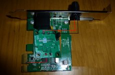
Here is my current little DIY project, not very advanced 🙂
I took a cheap TP-Link PCIe network card, cut the 3.3v to PCIe/motherboard and replaced it with external power through a linear voltage board. The result so far is very good, sounds better than my battery driven switch.
I haven't cut the ground to PCIe though, I'm afraid it might prevent the card from functioning, but it would be preferable if it was possible.
However, to complete it I would like to replace the clock as well, so does anyone know of a low-phase noise quality clock for 25Mhz that can be ordered online and in quantity of 1?
Btw, if you don't believe that tweaks like this matter for sound, feel free to do that but please don't post about it here. Lets keep this an informative DIY post and not yet another flame-war about "bits are bits". Maybe the mods can help keep it clean?
Have a look at what I attached...
1. the photo shows how to position and wire up the LDOVR 1A 3.3V regulator
a) solder solid core copper wires to +3.3V DC rail and to the ground fill.
b) slide (open the eyelets first!) the LDOVR reg on to these wires, and then secure the reg on that big black IC. Solder the wires to be as short as possible.
c) use one of these: 35SEPF22M (22uF/35V). Solder this cap to OUT+ and OUT- outlets on reg board. Keep the legs as short as possible. You could actually, slide both the capacitor legs and the copper wires at the same time, through the eyelets, and then solder the whole lot in one go. The eyelets diameter is large enough. This will ensure the shortest wiring. NOTE: that LDOVR reg needs to see some capacitance at its output to perform at its best. Just be sure to keep the capacitor legs as short as possible.
2. Once you move to DAC xtals/ oscillators, always go with NDK; much better than the competition. See the document I attached. Also, go straight to SDA types, which have much better phase noise at crucial frequencies of 1Hz, and below. They are difficult to find in quantities of 1, but search the net and you'll find them. See the pdf attached!
The above will keep you occupied for a while. Continue playing, experimenting, reading and...learning. The mod I suggested will give you very good results. Let us know what you think...
Good luck,
Nick
PS
I just saw mterbekke's post... do not cut any ground copper fills...
Attachments
Last edited:
You don't happen to live in Stockholm, Sweden? If so, you are welcome to come listen to my "goofy" mods and compare them to a regular switch. I can promise you one thing; you would be surprised 🙂
Oh boy. After all these remarks, you still think most of these good intended remarks about what you can not do, shouldn't do, have to do, has no point, convincing you of the meaningless "because that's how networks work" and trying to "educate" you, you think you could prove to them the results by ear?
Haha, of course not!
Never trust your ears!
The OP tried to present this DIY-endeavour as a project he was interested in, just for the fun of it. Instead of helping the guy out with knowledge how to approach, implement and execute best and do the things he wants to accomplish, all I read are remarks from guys who either talk about their own opinion (theoretical standpoint, this is practice), ridicule, see black and white (isolation and balanced signalling mitigate all forms of any "noise"(whatever noise means)) to measurements only possible if access to extremely expensive equipment, which can only generate reliable data if operated by an expert?
This is clearly not the intent, nor fruitfull for any of us here and I don't see the point.
If the OP's goal would be, for instance, to make a commercial product and go about like this, advertising it as the best NIC ever and charge 100's of dollars/euro's for ir, making snake oil, I get the idea of ridiculing somewhat.
Either way, this should be a place to learn, experiment and help out.
You should.
Cheers, I won't 🙂 I had a feeling it was a bad idea but had to make sure.One thing you should definitely NOT do is cut ANY ground going from the motherboard to the card.
Oh boy. After all these remarks, you still think most of these good intended remarks about what you can not do, shouldn't do, have to do, has no point, convincing you of the meaningless "because that's how networks work" and trying to "educate" you, you think you could prove to them the results by ear?
Haha, of course not!
Never trust your ears!
The OP tried to present this DIY-endeavour as a project he was interested in, just for the fun of it. Instead of helping the guy out with knowledge how to approach, implement and execute best and do the things he wants to accomplish, all I read are remarks from guys who either talk about their own opinion (theoretical standpoint, this is practice), ridicule, see black and white (isolation and balanced signalling mitigate all forms of any "noise"(whatever noise means)) to measurements only possible if access to extremely expensive equipment, which can only generate reliable data if operated by an expert?
Yet, he ignored all the advice by people who understand the inner workings of the physical layer of an ethernet interface and the electronic theory on how these devices function.
Either way, this should be a place to learn, experiment and help out.
You should.
True, but it doesn't mean you can ignore the laws of physics, electronic circuit theory and standards on how equipment and devices need to conform with to communicate over ethernet networks simply because it doesn't conform to a personal belief system.
The OP would have saved us all a lot of time by just understanding the information that was being imparted rather than refuting it.
The IEEE 802.3 standard is your friend.
Sometimes it helps to know the rules before you break them, other times you surprise yourself.
Have you played around with ferrites before?
Have you played around with ferrites before?
Cheers for the help, I will do the capacitor fix but think I will leave the reg board as it is (its so nicely glued there on the top) 🙂 I use solid OCC coppar (Neotech), leftover from some cables I made, awg 18, so its not like an inch of extra cable will matter muchHave a look at what I attached...
1. the photo shows how to position and wire up the LDOVR 1A 3.3V regulator
a) solder solid core copper wires to +3.3V DC rail and to the ground fill.
b) slide (open the eyelets first!) the LDOVR reg on to these wires, and then secure the reg on that big black IC. Solder the wires to be as short as possible.
c) use one of these: 35SEPF22M (22uF/35V). Solder this cap to OUT+ and OUT- outlets on reg board. Keep the legs as short as possible. You could actually, slide both the capacitor legs and the copper wires at the same time, through the eyelets, and then solder the whole lot in one go. The eyelets diameter is large enough. This will ensure the shortest wiring. NOTE: that LDOVR reg needs to see some capacitance at its output to perform at its best. Just be sure to keep the capacitor legs as short as possible.
2. Once you move to DAC xtals/ oscillators, always go with NDK; much better than the competition. See the document I attached. Also, go straight to SDA types, which have much better phase noise at crucial frequencies of 1Hz, and below. They are difficult to find in quantities of 1, but search the net and you'll find them. See the pdf attached!
The above will keep you occupied for a while. Continue playing, experimenting, reading and...learning. The mod I suggested will give you very good results. Let us know what you think...
Good luck,
Nick
PS
I just saw mterbekke's post... do not cut any ground copper fills...
I use an NDK already, in my DAC (RME ADI-2 has this one NZ2520SDA(Ultra Low Phase Noise Type)/Crystal Clock Oscillators/NDK ) but I could not find the SDA in 25 Mhz, but NZ2520SD (without A) can be ordered from Japan though, see link below:
NZ2520SD-25.000000M-NSA3449E 日本電波工業 | タイミングデバイス | 水晶発振器(SPXO) | Nihon Dempa Kogyo (NDK) - チップワンストップ 電子部品半導体通販サイト
Last edited:
No, but I read that they can help. I power my digital stuff from batteries with short cables so don't think they will do much in that case.Sometimes it helps to know the rules before you break them, other times you surprise yourself.
Have you played around with ferrites before?
- Status
- Not open for further replies.
- Home
- Source & Line
- Digital Source
- Low-phase noice clock for ethernet, 25Mhz