I managed to short the output of one of the rails of my dual Studer 900. Now it isn't playing ball. What might be the failure mode of a short on the output of one of these Chinese studer 900s? . thanks 👍🏻
Hello everyone.
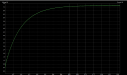
Aliexpress v1.2 board is taking ~6.5s to reach 21V on the output with 23.6V on the input bulk cap. This is not reasonable for my use case.
Thanks to this post (other schematics shared by the members aren't accurate, for the v1.2 that is) I figured it's the C4 and C5 that define the run-up time. Replacing original 47uf with 1uf caps shortens the run-up time to ~0.25s.
Cheers
I have recently purchased a version with a new board layout which has a larger heatsink and a variable resistor to set the main voltage. It also has quite a bit of room for upgrading the caps which I have done (as well as fitting a proper earth connection to the chassis). Here is the original version before modification.
View attachment 1173290
Here is the modified version.
View attachment 1173291
Replacing original 47uf with 1uf caps shortens the run-up time to ~0.25s.
Cheer
Thanks Igor, will try it
Hi Ronnie, will you please share in more details the modes you have applied in order to copy them, thanks😉
Have replaced the opamp with a LME49720 Dual High Performance, high fidelity and paralelled the existing caps with 220 nano NOS polystirene
Hi everyone, I'm planning to build a PSU for my DAC and Headphone AMP based on the Studer 900 schematics found here.
Do any of you have an "improved/ new version" schematic that I could use in KiCad? (Or replicate)
I need a 24V ~1A and a 5V ~1A output.
These can come from two total separate boards and transformers, I don't mind.
If I don't need variable output which parts should I exclude from the schematic?
I'm a total newbie in this area, sorry if I'm asking someting stupid.
Thank you!
If wanting to lock in a voltage with only slight tuning adjustment, you can:
- use PCB version 1.2 and only has one trim pot and one voltage set resistor (RB).
- For other versions of the PCB use a combination of 2-3 resistors to set the main voltage (L, M, H). The seller description often tells how to use them to set the right voltage or use this post no.68.
- For the boards with the the large shared heatsink like the one pictured above, replace the top trim pot with the 2-3 resistors above.
Thanks for the quick answer, but I don't want to order the PCB, I'd rather make it myself. Shipping from Ali usually takes 1+ months, I don't want to wait that much if possible.
Isn't there a schematic for that 1.2 Version? I couldn't find it.
For trasnformers I was thinking either a Myrra 30VA PCB mounted, or a 35VA toroidal.
+I forgot to ask this directly, but is it even possible to make a 5V output version of this?
Isn't there a schematic for that 1.2 Version? I couldn't find it.
For trasnformers I was thinking either a Myrra 30VA PCB mounted, or a 35VA toroidal.
+I forgot to ask this directly, but is it even possible to make a 5V output version of this?
There a couple of schematics in this thread of v1.1 with an improved physical layout to the chinese boards, but none of v1.2.
A 5V version can easily be made using a 9V output transformer. You can use a 10V but the 9V runs cooler and is the minimum that will work.
A 5V version can easily be made using a 9V output transformer. You can use a 10V but the 9V runs cooler and is the minimum that will work.
Hello ! If I need to get from it 12V 2A but also I want to have opportunity to test it with another 15V device then I need 15V transformer, right? It will be 21V DC at input, Isn't the voltage drop too large for a stabilizer with a 12V output at a load current of 2A? May be this is bad idea to have simultaneously 15V for tests on this board?
Yeah I've rotated that, and corrected some connection errors, but somehow I made it worsethe 5V1 zener is drawn the wrong way around in that schematic
I guess it's going to be easier to make a new one, I'll try to copy #385, but I'm not sure what CON1 and CN2 is for.
Attachments
CON1 is yours F_OUT with ground and CN2 is absend on that board, just connect cn2 to VCC and GNDI'm not sure what CON1 and CN2 is for.
Thank you,
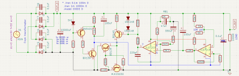
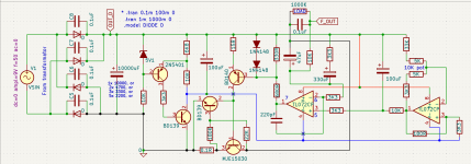
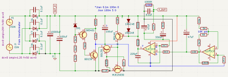
I tried my best to replicate the schematic, but it still doesn't seem to work.
Is it the makeshift 10K potmeter? I tried changing its values, but didnt seem to do anything.
I traced down every route, but I didn't find any errors, hopefully I'm just blind and its something put in reverse again.
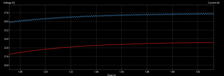
Blue line is OUT_D (From Diodes + 10kuF cap), Red line is the output.
I tried my best to replicate the schematic, but it still doesn't seem to work.
Is it the makeshift 10K potmeter? I tried changing its values, but didnt seem to do anything.
I traced down every route, but I didn't find any errors, hopefully I'm just blind and its something put in reverse again.
Blue line is OUT_D (From Diodes + 10kuF cap), Red line is the output.
Attachments
- Home
- Amplifiers
- Power Supplies
- low noise Pre-Amp / DAC power supply MJE15034 TL072 Regulator based on STUDER 900