I have tried today to verfy the maximum current this circuit can deliver.
So I have set up the output voltage to 18 VDC.
POwer transformer is a 100VA dual 15AC with max 3.33 A for both secodary pair.
I have removed R111 to not limit Vce of the power bjt Q104 ( in my case TIP31C Ic max 3 A).
Then I have shorted R109 .
The BD140 (Q105) which control the base of Q104 has two diodes with limit its Vbe. I have removed one of them.
Well with 50W Load resistor 8.2 Ohm and 18VDC I expected 2.19A...but the regulator could rech just ca 15V...and the BD140 was getting very hot. I have turned of the circuit otherwise it would have been burnt.
This BJT schould pump current in the base of the power BJT.... but it can´t and it becomes very hot...
I do not understand what is happening. can someone help?
The limit resistor is 0.22 Ohm
I would reach 4 A of course with a D44H11... but there is this limitation which I do not understand. Thanks
I solved the problem. 15AC transformer has too low unregulated voltage.
I replaced it with a 80VA 22AC and everything worked like magic.
I managed to have in output 3.75 A with 18.05 V voltage.
Hi
+1 about gerber for sharing
very satisfied about performance in SQ. I use the chinese board and thanks to recommendations from bbutcher to set it up with 5V output (transfo 30VA-2x9Vac), it powers well my DDC (usb in - spdif out) either Singxer F-1 Xmos or Xingcore U30 or LJM CM6631A.
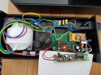
Only one key weakness is the huge overvoltage at power on. I get about 28v peak during 0.4s and it is enough to hang up my DDC. I was obliged to make a Timer On Delay circuit (about 8s delay) at output to protect devices (see picture)
Does someone know how to lower this issue on circuit board w/o need of add-on Timer On Delay circuit?
Thks
+1 about gerber for sharing
very satisfied about performance in SQ. I use the chinese board and thanks to recommendations from bbutcher to set it up with 5V output (transfo 30VA-2x9Vac), it powers well my DDC (usb in - spdif out) either Singxer F-1 Xmos or Xingcore U30 or LJM CM6631A.
Only one key weakness is the huge overvoltage at power on. I get about 28v peak during 0.4s and it is enough to hang up my DDC. I was obliged to make a Timer On Delay circuit (about 8s delay) at output to protect devices (see picture)
Does someone know how to lower this issue on circuit board w/o need of add-on Timer On Delay circuit?
Thks
Attachments
You need t remove teh 1N4148 diode otherwise is the base current of BD140 limited and it cannot open the MJE15034 any more.
At the same time you had to remove the block on the Vce of the MJE15034:
short R109 and open R111.
You will reach 2 A without any difficulties.
I changed the 15ohm by a 6R8 resistor. Didnt remove the diodes. so Ib = 100mA.
Changed the MJE15034 by a MJE15030 which give 3A by Ib=80mA.
Also replaced the 6800uF by a 22 000uf for more stability.
Everything works perfect. 🙂
Well, there really is no problem with a gerber. Even someone who does not understand it can be traced in 2 hours. It's just weird. Upload photos with track sizes and do not attach the file itself ...
I actually have another question about the transformer. I don’t understand which one is necessary. I need to get 24v at the output a little more is not prohibited and between 0.4-0.5A. What kind of transformer is needed for this so as not to heat the chip itself and not fiddle with the current-limiting resistor, and stable work. Say a 24v 15W transformator is enough for my needs? Idle 26v. after the capacitor multiply 1.41 and get 36.66v. This is enough for stable operation and the chip will have to dissipate heat about 6.3. I think a standard radiator will do it. Soldering jumper "H"
and set the tension I need. And what about the Strength, how much the current will fall after the board, it will be in the range of 0.4-0.5a well, if it is higher, then I can limit it by replacing the resistor. what is the current drop on the board?
Ps: This is the reasoning. I'm not a techie, I have a different education. thanks
Ok, I’m hoping someone here can point out where I’m being an idiot. I had both sides of this PSU running independently for months last year but now I need it to run bipolar for my BA2018 line stage. I’m getting a solid 21VDC out of one side and nothing out of the other, plus one particular resistor on that side is frying repeatedly.
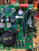
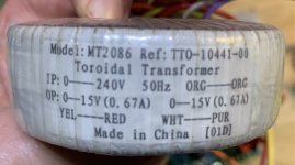
Here’s a photo of what the faulty side looks like. Please don’t laugh (or do but not where I can hear) at the soldering. This was the first I’d done in like 30 years. I’ve circled the resistor that keeps getting fried and included a photo of the transformer I’m using.
I’d appreciate any thoughts or advice as I can’t move forward with the line stage until I get this sorted. Thanks
Attachments
I would recomment a transfo of minimum 25VA.Well, there really is no problem with a gerber. Even someone who does not understand it can be traced in 2 hours. It's just weird. Upload photos with track sizes and do not attach the file itself ...
I actually have another question about the transformer. I don’t understand which one is necessary. I need to get 24v at the output a little more is not prohibited and between 0.4-0.5A. What kind of transformer is needed for this so as not to heat the chip itself and not fiddle with the current-limiting resistor, and stable work. Say a 24v 15W transformator is enough for my needs? Idle 26v. after the capacitor multiply 1.41 and get 36.66v. This is enough for stable operation and the chip will have to dissipate heat about 6.3. I think a standard radiator will do it. Soldering jumper "H"
and set the tension I need. And what about the Strength, how much the current will fall after the board, it will be in the range of 0.4-0.5a well, if it is higher, then I can limit it by replacing the resistor. what is the current drop on the board?
Ps: This is the reasoning. I'm not a techie, I have a different education. thanks
High current modification solved
Hello I just someone asked me which modification did I do to reach high current at 18VDC Output.
I started from the original scheme you can find in older posts. I redraw it in Eagle and made a PCB with wider tracks.
Attached you see the scheme "Alimentatore Studer900 S".
I tested the Power supply with a load, which consisted of 2 50W resistors of 8.2 Ohm working in parallel.
Following modifications are needed (names are referred to the attached pdf).
- Diodes D6/D7 These switching diodes fixed the maximum voltage accross R9 and therefore also between R7 limiting the current flowing in the emitter of Q5.
This will limit the base current of the power BJT Q4 , which cannot deliver then the required current.
So simply do not mount them or remove them. - We have to remove the constraint of the maximum dissipated power for Q4. As already butcher wrote remove R8 and R6. Leave an open circuit instead of R8.
Instead of R6 make a short circuit. In this way Q3 will close Q4 based limiting the current with R5 with the usual formula Max I = ~0,65V/R5 - At the beginning I was not sure that the voltage reference (phantom voltage) of the Op amp was enough to have in the output PIN7 an high voltage to open Q5 . So I added To the 5,1V Zener two green Leds (it can be also red) . In this way I have a power voltage for the Op amp of about 16/17V . I do not remember precisely. In this way I am sure that when needed the output voltage will be big enough to open Q5.
So simply add in series 2 Leds. Keep in mind this will work if the unregulated voltage is bigger than the phantom voltage. Here I am supposing you are using 22VAC or bigger to have 18VDC output. That means 22*1,44 =31V. - The PNP BD140 (Q5) has a low HFE, so it cannot deliver so much current in the base of Q4. I have replaced it with a PNP Darlington BDX54C.
This worked very well. I just picked up from shop what they had on stock. Maybe there better Darlington PNP. I have put also a small heat sink on it. - I used two 15 Ohm resistor in Parallel for R7.
- You should check also the current flowing in LED1 which is the reference of the comparator. I did not changed R23 3,3K, but if we rise the voltage of teh phantom regulator with the two green led like at written above, then we should choose R23 so that the current of LED1 is about 2 mA.
For example with the Standard phantom voltage is about 10.7V --> (10,7-1,7V)/3300= 2,5 mA. If we rise the voltage of the phantom then it is (18-1,7)/3300= 4,9 mA a bit to high for the Led . Just try with 6.8k or 10k. - Change the rectifier diodes with ones with higher Ampere Rate. I have some which are for 10A, but they are running very hot. I would go at least for 16 Ampere and if you have heat sink it is better.
- Most important and it was my biggest mistake: for 18VDC use at least 22AC transformer. I was trying with 15AC transformer because I wanted to have the minium dissipation on Q4. The rectifier diodes an the transformer were always over the limit because in a little fraction of the sinus they had to load all capacitors and deliver the current to the load. I fried the 10A diodes and transformer were vibrating like a washing machine.
- to operate with reliability around 4 A replace Tip 41c with for example D44H11TU NPN BJT. It has a maximum rating of 10A and the HFe values of the datasheet are taken at 4 A . Take a big heat sink for this or connect it to the metal case directly.
Attachments
Ok, I’m hoping someone here can point out where I’m being an idiot. I had both sides of this PSU running independently for months last year but now I need it to run bipolar for my BA2018 line stage. I’m getting a solid 21VDC out of one side and nothing out of the other, plus one particular resistor on that side is frying repeatedly.
Here’s a photo of what the faulty side looks like. Please don’t laugh (or do but not where I can hear) at the soldering. This was the first I’d done in like 30 years. I’ve circled the resistor that keeps getting fried and included a photo of the transformer I’m using.
I’d appreciate any thoughts or advice as I can’t move forward with the line stage until I get this sorted. Thanks
Well if i see right it seems to me a 10 Ohm resistor, the one which limit the emitter current of BD140 PNP.
Do you have a transformer with 15VAC secondary? if yes that is roughly 21,6 V unregulated voltage. You will fry also the transformer and diodes to have 21VDC output. You have too less time to load capacitors and deliver current to load. Maybe the load you have is really small and this did not happened yet.
Not only the resistor fries but also the PNP BD140 should be very hot and small like burnt.
Change transformer to 24VAC and it will work.
With your transformer the BD 140 has to deliver very high current in the base of the MJE15034 in a very small fraction of the sinus....It is over the limit.
I have a 120va 230v to 2x30v toroid , as well as two studer900 that are assembled. I intend to make a double dc supply that will output 24v and 12 v. Will the studers accept that voltage and be able to output 24 v or 12v. Or will i fry the studers and would need a different toroid. And if so what secondary voltage should i go for?
Last edited:
Hello with 30VAC transformer you have 43.2 VDC unregulated. So if you want an output of 12VDC you will have a Delta voltage between emitter and collector of the MJE15034 of about 43.2-12= 31.2 V. So the dissipated power of the BJT will be P= 31.2* I where I is teh current of the load...with just 0.2A you have already 6.24 W to dissipate.
With 24V DC you have with I = 0.2A --> P= 3.84W.
With very low currente you have already big power to dissipate.
If the load required 1A you have already a oven.
I would use 22AC or 24AC transformer.
I think also that the NOver cap of the rectifier are only rated with 40 VDC and with 30VAC you are already over the limit.
hey guys, is it possible to replace the original opamp TL072 directly with something better likes MUSES01 or MUSES02 (Studer900 LPS)?
I did try dual ADA4627 as well as LT1057 but the LPS becomes hot and suddenly stop working without power on after 1 or 2 days using until i plugged the TL072 back to the circuit.
I did try dual ADA4627 as well as LT1057 but the LPS becomes hot and suddenly stop working without power on after 1 or 2 days using until i plugged the TL072 back to the circuit.
Attachments


I've tested a few different opamps - and the one I find best is the TLE2072. It makes a nice improvement to the sound.
Cheers,
narla
Cheers,
narla
A good PSU opamp is the OPA209. It is also used in Placid HD. I've had great results with the successor OPA2210.hey guys, is it possible to replace the original opamp TL072 directly with something better likes MUSES01 or MUSES02 (Studer900 LPS)?
I did try dual ADA4627 as well as LT1057 but the LPS becomes hot and suddenly stop working without power on after 1 or 2 days using until i plugged the TL072 back to the circuit.
The AD825 is highly recommended for the "Jung/Didden super regulator", has anyone here tried that one for this regulator ?
You may want to note that chinese suppliers are now offering a version 1.2 board with improved traces -- ran across it on the 'bay.
They've also simplified the voltage range setting to one resistor ('RB') rather than a bank of three.
The trace layouts are different though the component layout and board size are the same -- meaning there's NO additional space for a larger filter capacitor or output capacitor, sadly.
They've also simplified the voltage range setting to one resistor ('RB') rather than a bank of three.
The trace layouts are different though the component layout and board size are the same -- meaning there's NO additional space for a larger filter capacitor or output capacitor, sadly.
Last edited:
I have recently purchased a version with a new board layout which has a larger heatsink and a variable resistor to set the main voltage. It also has quite a bit of room for upgrading the caps which I have done (as well as fitting a proper earth connection to the chassis). Here is the original version before modification.

Here is the modified version.

Here is the modified version.

- Home
- Amplifiers
- Power Supplies
- low noise Pre-Amp / DAC power supply MJE15034 TL072 Regulator based on STUDER 900