Also is a plot of the Jtest test at 44.1 over I2S.
Did you feed the JTest signal as an 16 bit? In my opinion may not..
Otherwise the LSB toggle signal is within marketing bits... 😀
Hp
That is a question for Alex. I tried the 16, 24 and 32 bit settings and saw no difference. There is some activity at the 224 Hz region. We will need Alex's input to know what its doing.
That is a question for Alex. I tried the 16, 24 and 32 bit settings and saw no difference. There is some activity at the 224 Hz region. We will need Alex's input to know what its doing.
I generate the following sequence for 32 bit:
0xC0000000, 0xC0000000, 0x40000000, 0x40000000 - 24 times,
then:
0xBFFFFFFF, 0xBFFFFFFF, 0x3FFFFFFF, 0x3FFFFFFF - 24 times.
For 24 bit the constants are 0xC00000, 0x400000, 0xBFFFFF and 0x3FFFFF and for 16 bit: 0xC000, 0x4000, 0xBFFF and 0x3FFF
for 16 bit.
I will check again what is really transmitted.
Alex-
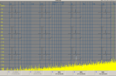
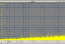
You may have a problem with the Jtest. Here is a digital link from the generator to the SPDIF in of the EMU 1616M. Source set to 16 bits. No sign of the LSB switching. It should have the 48K and a 1K LSB at 16 bits. Same at all the other options I tried.
You may have a problem with the Jtest. Here is a digital link from the generator to the SPDIF in of the EMU 1616M. Source set to 16 bits. No sign of the LSB switching. It should have the 48K and a 1K LSB at 16 bits. Same at all the other options I tried.
Attachments
1audio-
I will check with logic analyser I2S signals.
Meanwhile, if you are already have PC connection, you can make a record to file to see the data.
I will check with logic analyser I2S signals.
Meanwhile, if you are already have PC connection, you can make a record to file to see the data.
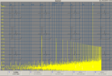
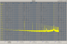
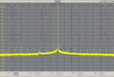
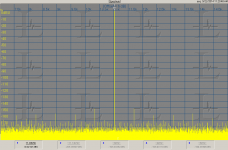
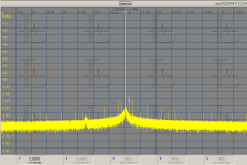
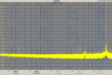
Jtest fixed. Alex found a bug and fixed it. Attached are digital and analog spectra of both 16 bit and 24 bit Jtest. The 32 bit is actually beyond academic for various reasons. This shows that even 24 bit LSB stuff is invisible.
The 16 bit tests were with a 100K FFT and 10 averages. The 24 bit were 1M point FFT's and 4 averages (I don't have the patience for 10 averages). The last plot is the AK4490 with the 24 bit Jtest. You can just see the LSB at 229 Hz and -135 dB. The harmonics will all be way below the resolution floor of a 24 bit system (and to my knowledge there are no 24 bit accurate DACs that can process audio, they are all too slow).
The 16 bit tests were with a 100K FFT and 10 averages. The 24 bit were 1M point FFT's and 4 averages (I don't have the patience for 10 averages). The last plot is the AK4490 with the 24 bit Jtest. You can just see the LSB at 229 Hz and -135 dB. The harmonics will all be way below the resolution floor of a 24 bit system (and to my knowledge there are no 24 bit accurate DACs that can process audio, they are all too slow).
Attachments
-
 JK gen SPDIF 44-16 fixed to EMU1616m.PNG86.4 KB · Views: 253
 -
 JK gen I2S 44-16 fixed to AKD4490.PNG80.9 KB · Views: 252
 -
 JK gen I2S 44-16 fixed to AKD4490 linear spectrum.PNG55.1 KB · Views: 252
 -
 JK gen SPDIF 44-24 fixed to EMU1616m log spectrum.PNG66.3 KB · Views: 248
 -
 JK gen SPDIF 44-24 fixed to EMU1616m linear spectrum.PNG58.3 KB · Views: 101
 -
 JK gen I2S 44-24 fixed to AKD4490 linear spectrum.PNG55.4 KB · Views: 100
 -
 JK gen I2S 44-24 fixed to AKD4490 log spectrum.PNG61.7 KB · Views: 98
Jtest fixed. Alex found a bug and fixed it.
Ohh, it was a shame bug - I simply comment the part of code when worked with new signal shapes, and forget to uncomment it....
The last 3.4.09 fw released at 20 Sept. 2014 with the following changes:
3.4.09:
- ConstValue signal added to DoP/DSD Modes
- DSD Shapes: 1002Hz Triangle and Square Waves, -3dB
- DSD Shapes: 441, 1002, 11025, 22050 and 44100 Hz Sine Wave, -3dB
- Pink Noise processing improved, now no 94kHz Fs limit
- LF Frequency Mode (1mHz-1kHz) added
- Frequency set changed from "Pos/Fix" to "Pos/Fix/LF"
- Channel switch:
was: L+R in-phase, L-R out of phase, Left only, Righ only, Mute
added: LxR Orthogonal signals (90 degree phase shift)
- Dig. Attenuation accuracy improved
Hi,
I am currently using the generator and I find it wonderful!! It must be in every lab that works with digital audio.
I have a couple requests for Alex for the next firmware releases:
1) Fix the rotary encoder but I know he is already working on it.
2) Choose between lin and log for sine sweep
3) Choose the sweep speed
4) Choose the start and stop frequency for the sweep
I apologize if it is already possible. I did not find trace of this nor into the instruction manual nor fiddling with the generator.
Best regards
D.
Hello friends,
I just made a new firmware, Version 3.4.11b, you can download from: Downloads - ALTOR AUDIO
danils - you items 3 and 4 are OK now.
Major changes:
- before you were able to save the current configuration to setups N1..8, and then download. Load from setup N=0 restore default configuration.
After power up the defaults configuration used.
- now setup N=0 is save "write only" :
a) you can save the current configuration to setup N=0, and it will be restored at the next power up,
b) load from setup N=0 will restore defaults.
Other setups, 1-9 are for save/load. Default configuration is pre-programmed for all setups (0..9).
Who has downloaded the last firmware and cannot make an uprgade - please redownload it again from my site. Sorry.
Some people ask me to add the regular functional generator up to some megaherz.
I make a prototype, the simplest is with AD5930 runnig from 24.567MHz clock and producing continuour, burst or sweepSine Wave, Trianlgle at one output, Square Wave an another output, which can be also the sweep strobe.
SQ Wave/Strobe are LVCMOS level (unipolar 0-3.3v)
Analog output is bipolar inside +/-5V rails.
It is possible to adjust the amplitude and zero shift.The main problem is that with AD5930 and 24.567MHz clock, the output frequency can be from 1.46Hz with the same step, up to 3-5MHz.
Prototype that I've made is designed as upgrade module to the existing generator, SPDIF and SPDIF-TTL RCA connectors are switched from SPDIF functions in "Audio Mode" to SIN/TRI and SQ signals in "Func. Mode".
And the main question - is it really need to implement it to this project?
It will increase the BOM ~$20-30.
There are a lot of simple and cheep functional generators at the market, so is it make a sence to continue with this module? It requers to finalize schematic R&D, to make PCB and some part of firmware.
Yes that does look interesting....altor said:
Here is the new link for it on your page (You might wanna put this in your OPENING POST on this thread 🙂)
www.altor.co/products/test-equipment/jkgen
This does analogue also right?? 🙂
Yes that does look interesting....
Here is the new link for it on your page (You might wanna put this in your OPENING POST on this thread 🙂)
Done!
It was not editable before.
Yes, there is PCM5102A DAC at analogue output.
Hi,
I use the 3.4.11 Beta edition.
Sometimes, I use the analogue outputs for signal source.
I see that there is no any real digital attenuation at jitter test unlike the attenuation menu - all the levels are 0dB!
Have it see that?
Additionally, is that better the digital attenuation to be 1dB step in 0...-30dB range and 10 dB step after?
Last edited:
Hi Lemon,
yes, you are right - at J-Test there is no attenuation. I simply forget to disable the menu.
In general, attenuation is 1dB step in 0...-20dB range, then 10dB down to -90dB.
It was the user's desire, but of course I can extend the 1dB step from -20 to -30dB.
BTW, I just finished my new DAC, this generator helps a lot!
Last edited:
Thanks for the info Alex.
Some from us use this marvelous device and as analogue signal generator.
For low measurements (Vrms), I think the dB extending to -30dB will be good.
If that can be done and with J test, it is welcome!
The new DAC! As independent device or we can upgrade the internal dac of this device?
Some from us use this marvelous device and as analogue signal generator.
For low measurements (Vrms), I think the dB extending to -30dB will be good.
If that can be done and with J test, it is welcome!
The new DAC! As independent device or we can upgrade the internal dac of this device?
- Home
- Design & Build
- Equipment & Tools
- Low Frequency Analog and Digital Signal Generator