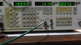
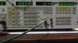
If one wants a low distortion of .005x% THD (16bit), you can just buy a Hamtek HDG2012B and get a function/arbitrary generator thrown in.
IMO---cheap for all it does --- $279.
THx-RNMarsh
If I'm not missing something, they quote <0.1% THD for the entire HDG2000 Family:
In theory you should be able to get very low distortion but a DAC that can run at 100 MHz will have some compromises to get there. Its a great device in any case. However do not expect it to replace a premium synthesizer (-110 dB @ 10 KHz is just OK as a source). it would be a great ARB and you could synthesize a digital audio serial waveform with lots of degradation if you need to test a receiver.
If I'm not missing something, they quote <0.1% THD for the entire HDG2000 Family:
The results (.005%) are measured... not spec. It is a very good generator with outputs most such instru do not provide; including wide band white noise at the push of a button.
THx-RNMarsh
The results (.005%) are measured... not spec. It is a very good generator with outputs most such instru do not provide; including wide band white noise at the push of a button.
THx-RNMarsh
Hi RNMarsh,
Frequency range where distortion is equal or below 0.005% ?
Measurement bandwidth (included harmonics)?
Hi RNMarsh,
Frequency range where distortion is equal or below 0.005% ?
Measurement bandwidth (included harmonics)?
whole range.... up to 100KHz of the distortion analyzer.
Example:
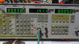
However, like we have discussed before, if you put the signal through a LP filter (or BP) you can cut the harmonics further.
Example: Using 50KHz signal and a 80KHz LP filter;
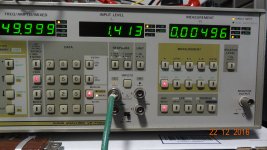 No filter.
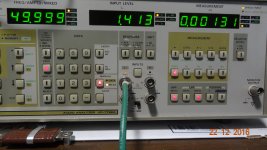
[analyzer FFT sums the first 5 harmonics for THD.
BTW -- 2H and 3H are equal amounts]
THx-RNMarsh
Last edited:
whole range.... up to 100KHz of the distortion analyzer.
Example:
View attachment 587075
However, like we have discussed before, if you put the signal through a LP filter (or BP) you can cut the harmonics further.
Example: Using 50KHz signal and a 80KHz LP filter;
View attachment 587077 No filter.
View attachment 587078
[analyzer FFT sums the first 5 harmonics for THD.
BTW -- 2H and 3H are equal amounts]
THx-RNMarsh
Great!
Thanks for sharing.
Thank you for the information & the measurements.The results (.005%) are measured... not spec. It is a very good generator with outputs most such instru do not provide; including wide band white noise at the push of a button.
THx-RNMarsh
It appears that the manufacturer is not aware of the true performance level of the instrument.
Regards,
Braca
probably a typo error... thd should have read < .01% which would usually mean typical is 1/2 that amount..... which is also consistent with 16 bits.
THx-RNMarsh
THx-RNMarsh
Last edited:
That's a pretty big difference. All types of analyzers will give different answers depending on where or what filters are engaged.
-Chris
-Chris
Richard are these THD numbers rather than THD+N.
The filters don't weigh as much with THD other than harmonic inclusion.
The filters don't weigh as much with THD other than harmonic inclusion.
Some freshly measured data of the capacitors distortions. Three or more pcs of the each type was measured in this schematic:
http://content6-foto.inbox.lv/albums/e/elterra/CapsC/CapsMeas.jpg
1) Kemet 1206 200V 0.01uF COG – 3 pcs measured
All are similar:
http://content6-foto.inbox.lv/albums/e/elterra/CapsC/200V1206.jpg
2) TDK 1206 630V 0.01uF COG – 6 pcs measured
1 best:
http://content6-foto.inbox.lv/albums/e/elterra/CapsC/630V1206best.jpg
4 similar results:
http://content6-foto.inbox.lv/albums/e/elterra/CapsC/630V1206mid.jpg
1 worst:
http://content6-foto.inbox.lv/albums/e/elterra/CapsC/630V1206worst.jpg
3) Xicon 50V 0.01uF polystyrene – 10 pcs measured - unfortunately very different results
2 best:
http://content6-foto.inbox.lv/albums/e/elterra/CapsC/XiconBest.jpg
4 good:
http://content6-foto.inbox.lv/albums/e/elterra/CapsC/XiconGood.jpg
3 not so good:
http://content6-foto.inbox.lv/albums/e/elterra/CapsC/XiconNSGood.jpg
1 worst:
http://content6-foto.inbox.lv/albums/e/elterra/CapsC/XiconWorst.jpg
4) Wima FKP2 100V 0.01uF – 6 pcs measured
5 are similar:
http://content6-foto.inbox.lv/albums/e/elterra/CapsC/100VFKP10nFBest.jpg
One old example (many times soldered):
http://content6-foto.inbox.lv/albums/e/elterra/CapsC/100VFKP10nFWorst.jpg
5) Wima FKP2 63V 0.022uF– 5 pcs measured
All are similar:
http://content6-foto.inbox.lv/albums/e/elterra/CapsC/63VFKP22nF.jpg
6) Wima FKP2 100V 0.022uF– 5 pcs measured
All are similar:
http://content6-foto.inbox.lv/albums/e/elterra/CapsC/100VFKP22nF.jpg
7) LCR Components 63V 0.022uF polystyrene -5 pcs measured
All are similar:
http://content6-foto.inbox.lv/albums/e/elterra/CapsC/63VLCR22nF.jpg
Apology in advance for the sidetrack but all of the audio oscillator theory experts are here: how do you remove 2nd and 3rd harmonics from an audio oscillator?
I have a Leader LAG-126b that measures nicely except for 2nd and 3rd order harmonics that are about 80-85db below the output frequency.
Sent from my iPhone using Tapatalk
I have a Leader LAG-126b that measures nicely except for 2nd and 3rd order harmonics that are about 80-85db below the output frequency.
Sent from my iPhone using Tapatalk
1) makes me wonder what is contributing to the deviations for the same p/n samples tested?Some freshly measured data of the capacitors distortions. Three or more pcs of the each type was measured in this schematic:
2)As a base line, any data available for lower voltage COG MLCC, to see how they compare to the higher voltage varieties.
3) I go to Mouser and filter for mlcc based on your criteria for selection, I come up with 59 matches. Apart from your testing, how to chose which one is the best to use?
It would be nice to know exact what part numbers you tested.
http://ca.mouser.com/Passive-Compon...x4arcZ1ylo5rpZ1yzmotyZ1yxbokaZ1z0x6frZ1z0x6d8
One heck of a lot of test samples.
Most of the distortion reduction techniques reduce the distortion introduced by the level controller and gain control element.
Fist identify which is contributing what and how much.
My approach is to reduce or illuminate the cause rather than trying to null or cancel.
What you get from the oscillator core BP filter is minimal.
As far as the core is concerned then better components or better use of the components are key. Series strings of resistors and capacitors. This sort of thing. Lower distortion amplifier etc.
It would be nice to know exact what part numbers you tested.
Kemet 1206 0.01uF 200V COG - C1206C103J2GACAUTO - KEMET - SMD Multilayer Ceramic Capacitor, 1206 [3216 Metric], 0.01 µF, 200 V, ± 5%, C0G / NP0 | Farnell element14
TDK 1206 0.01uF 630V COG - http://eu.mouser.com/ProductDetail/...4crhq/rMFizRjNevi5Q6kpksgo8OKRdafV4Lnsh7wcwDd
Anatech and mark brown --- I am showing a way to lower the thd further. If you design a filter for a particular freq then the generators harmonics will be attenuated. Nothing to do with the analyzer. The filters in the analyzer were just used to show the principle of filtering 2H and above. Its an option for using a low cost generator and getting even lower thd.
THx-RNMarsh
THx-RNMarsh
Last edited:
THX, great info, pretty good for cheap easy to get mlcc caps.
More wondering, sorry just interested in your findings.
1) If larger sizes, >= 1210 perform any different?
2) Any way to tell from the datasheet, how well they will perform in this test?
3) performance differences, if you put a smaller COG in parallel (~1n0), like we do for supply decoupling/filtering
THX, great info, pretty good for cheap easy to get mlcc caps.
More wondering, sorry just interested in your findings.
1) If larger sizes, >= 1210 perform any different?
2) Any way to tell from the datasheet, how well they will perform in this test?
3) performance differences, if you put a smaller COG in parallel (~1n0), like we do for supply decoupling/filtering
In a theory, larger sizes may be better, but at this moment I haven't them.
Regarding SMD MLCC, I do not know a way for to get any knowledge about the distortions from the datasheet.
From my practice, metallized (polypropylene) film capacitors are not so good as foil-film capacitors.
Seems, that may be differences within the one part number examples. Then the paralleling can make an averaging effect of the distortions performance, and I do not think, that the smaller values distort less.
Hi Richard,
Yes, I got that.
-Chris
Yes, I got that.
Of course you're right in principle. In my experience, the less expensive oscillators aren't that stable in frequency, plus there is typically line based noise due to the cheaper power supplies used. You would have to use a lower Q filter and give up some reduction in order to allow use with a cheaper audio oscillator. We're talking about fixed frequency oscillators as well. It's a good idea for use with a wein bridge oscillator, cheap and cheerful. Wish I had thought of it!Its an option for using a low cost generator and getting even lower thd.
-Chris
- Home
- Design & Build
- Equipment & Tools
- Low-distortion Audio-range Oscillator
