Has anyone mentioned going "the other direction" for FFT syncing? Have the ADC driven by a PLL driven by the 1kHz sine oscillator?
It seems this should be (relatively) easy. From the time-nuts list, they have 10MHz precision frequency standards running from the 1 pulse per second output of a GPs receiver.
Good keyword: Frequency Standard. Corona Shut Down project ...
Attachments
Hi Jan,
This is a very good point worth looking into. I would observe, however, that the noise gain of the two integrators is just unity, and that op amp distortion degradation is usually in accordance with the noise gain.
That leaves the summer. It is not frequency dependent, and its noise gain is a little higher than 2. So when the SVF is operating at its fundamental with a gain of 10, the summer op amp is not really operating at a gain of ten insofar as its noise gain is concerned.
The gain of 10 at the fundamental is mainly due to the positive feedback of the global SVF loop reinforcing the gain. At frequencies away from the fundamental, that positive feedback begins to disappear. Also coming into the picture in a good way is that the BPF output comes after the first integrator, which attenuates harmonic distortion.
These questions could probably could be answered by a SPICE simulation using an op amp with some known distortion and furthermore looking at filter distortion with different BPF Q settings.
Cheers,
Bob
I agree.
And if I'm not mistaken, the low Q BPF filter plus global positive feedback would enjoy very similar noise gain. The noise gain of a low Q filter would be only slightly higher than an integrator. In contrast, a high Q single-opamp BPF would be at serious disadvantage re noise gain.
BTW, I love these technical discussions. Now retired, and aside from camaraderie, I most miss exploring with my colleagues the merits and disadvantages of competing design approaches. I hope I never offend anyone--- this is a great community.
Steve
Some soundcards could handle the variation in oscillator frequency but others not so well. You also have to factor the rate of change of the source. A constellation of GPS satellites defines stability. The RC oscillator really does not on these scales. Digital audio is supposed to be at 5 PPM and getting a system to trace well beyond that may be a challenge.
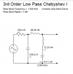
How much attenuation can be tolerated? The CLT-1 uses passive L/C filters to get to -170 dB. For 10 KHz the inductors are quite large. Still an LC filter with a sharp cutoff at 1500 Hz may be a realistic option.
Below is a "buildable" filter with a zero at 2 KHz and 35 dB attenuation above. I would be the first to say it will not be easy to build. Maybe JNeutron's toroid winder would be helpful here.
Attachments
Has anyone mentioned going "the other direction" for FFT syncing? Have the ADC driven by a PLL driven by the 1kHz sine oscillator?
This has crossed my mind but I wasn't sure what the consequences would be from a slowly drifting ADC clock as the oscillator drifts. Can't really get my head around it.
I think I am going to look into a bit more using an harmonic passive notch after a digital oscillator, red=oscillator, blue=with 3kHz passive t-t. Need to characterize the whole chain but looks promising.
Jan
Attachments
Last edited:
IMO clocking the soundcard with PLLed signal from the drifting oscillator would work OK. Many soundcards have SPDIF input which generates clock at least for the capturing part (and mostly for the DAC too). Some soundcards have external wordclock input, some even masterclock (256x Fs) input.
The receiver/transmitter in soundcards is clocked by the connected master (PCI, USB), the DAC/ADC have independent clock reading/writing to short buffers in the digital section.
The question is jitter of the PLL which directly affects sampling. Probably OK with modern clock chips.
The receiver/transmitter in soundcards is clocked by the connected master (PCI, USB), the DAC/ADC have independent clock reading/writing to short buffers in the digital section.
The question is jitter of the PLL which directly affects sampling. Probably OK with modern clock chips.
An example from a different application area may help here, namely that of rotating machinery.This has crossed my mind but I wasn't sure what the consequences would be from a slowly drifting ADC clock as the oscillator drifts. Can't really get my head around it.
Jan
For example, the instantaneous speed of an IC engine varies even within a single period (2 rotations in the case of a four-stroke engine). Acquiring whatever dynamic data on the engine with a fixed clock results in very smeared spectra. So the usual method is to have an angle encoder coupled with the crankshaft to clock the data acquisition (e.g. 1024 pulses per revolution).
The spectra obtained from such records are then not expressed in terms of frequency, but rather in terms of rotational order, hence the name of the method - Order Analysis.
The point is that all signal components that are harmonically related to the shaft rotation will produce sharp spikes in the spectrum.
So if the oscillator frequency would control the ADC clock, all harmonics produced by a DUT would stay in tune with the instantaneous oscillator frequency, i.e. appear as sharp peaks in the spectrum.
Hope this helps.
Regards,
Braca
The general rule is that the distortion becomes lower with a larger supply voltage. Do you have measurements?BTW - drop the PS total for Victor's osc/gen to 30vdc. It lowers the 3H by 6dB.
Every little bit counts.
When you lower the PSU to 30VDC:BTW - drop the PS total for Victor's osc/gen to 30vdc. It lowers the 3H by 6dB.
Every little bit counts.
The shunt regulators are out of current and not working,
Onboard supply voltage for the opamps and for the AGC reference becomes lower and may drift without the stabilization.
As result the output voltage also becomes lower and may drift.
Vic.
I can recommend the LME49870 data sheet. With +-22V supply there is lower THD than with +-15V or even +-5V.
When you lower the PSU to 30VDC:
The shunt regulators are out of current and not working,
Onboard supply voltage for the opamps and for the AGC reference becomes lower and may drift without the stabilization.
As result the output voltage also becomes lower and may drift.
Vic.
Are these TL431 shunt regulators important or are standard 7815/7915 voltage regulators sufficient?
The shunt regulators are used for to eliminate ground loops via the external PSU. Otherwise no matter.Are these TL431 shunt regulators important or are standard 7815/7915 voltage regulators sufficient?
Vic.
Victor, How would I or anytone adjust the shunt regulators if using yourThe shunt regulators are used for to eliminate ground loops via the external PSU. Otherwise no matter.
Vic.
oscillator with lower voltages? Is there a simple place to tack a pot somewhere?
Or to tack a variable cap somewhere?
Also, Vic, which other devices would be a drop in replacement for what you
are currently using? There's that NEW Ti opamp from BB.
Are any of the LMExxxxHA's possible for tacking on?
Would there be a large change if using an LME49813 for instance,
CFB yes?.
Or the little LME49999 soic device?
or the one diyralf mentioned above?
I am only asking because I don't know and now sure how to go about it.
Cheers,
You can see the actual schematic:Victor, How would I or anytone adjust the shunt regulators if using your oscillator with lower voltages? Is there a simple place to tack a pot somewhere?
Or to tack a variable cap somewhere?
Also, Vic, which other devices would be a drop in replacement for what you
are currently using? There's that NEW Ti opamp from BB.
Are any of the LMExxxxHA's possible for tacking on?
Would there be a large change if using an LME49813 for instance,
CFB yes?.
Or the little LME49999 soic device?
or the one diyralf mentioned above?
I am only asking because I don't know and now sure how to go about it.
Cheers,
https://content22-foto.inbox.lv/albums/e/elterra/OscillatorNew/Gen1kHzN7.png
If you wish to use lower voltage, you need to keep the 25mA current from the external supply. So, the resistors R32, R33 must be changed. If you wish to run onboard shunt stabilizers at lower voltage, you need to change the R22, R24 for less value, but it is your own risk to get lower performance.
There is no simple solution for to place a pot or variable cap in the schematic, if you meant to change the frequency.
Vic.
The bigger issue where the TL072 is used would be DC stability and accuracy. Its noise contribution in the AGC where it is would be really small. A precision FET opamp might help but the DC reference is not good enough to really show a benefit.
R14,R15 is near the MMBF4391 (SOT23). The value may be lower than in in the schematic - latest update 33 ohm....TL072 opamp..... can that be changed to lower LF noise part and will that help lower the LF noise output level? Also, where is R14, 15 on PCB?
Probably you won't see the difference, if the TL072 will be changed.
Vic.
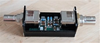
Slightly OT: After building several single-ended twin-tees, I have a dozen PCBs left. I wrote up the whole thing including small case etc, see attached.
Anybody wants any, let me know, € 10 including shipping anywhere in Europe for the time being (shipping oversees from Belgium carries a € 50 premium fee ...).
Jan
Anybody wants any, let me know, € 10 including shipping anywhere in Europe for the time being (shipping oversees from Belgium carries a € 50 premium fee ...).
Jan
Attachments

- Home
- Design & Build
- Equipment & Tools
- Low-distortion Audio-range Oscillator