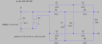
There is the very small signal across the FET. Less than 0,5% of the full signal.
RF materials are very expensive, but the main problem was the quality of the solder mask , not the board material. So, soon we will see how the new boards run.
What is the actual typical range of voltage across the JFET?
Cheers,
Bob
No, not only the opamp limits the performance, especially at 1kHz. The capacitors also can make some effect (sometimes I need to remove "bad" caps from the boards), and the board mask quality, too. It is very hard to get the performance stable under -160dB. Not all the 1kHz boards can run that. I claim under -150db, but real limit is around -155dB. Now I am waiting for new PCBs, where some sensitive areas will be without the mask.
Please add me to your list. I need/want the best you can do.
THx-RNMarsh
About a generation ago Tektronix identified an issue with PCBs and high impedaces they called "hook" from the distortion it created. I suspect it may still be an issue. Tektronix went to an exotic pc material to deal with it. Not one of the usuals. It was clear, no fiberglass inside.
I can see solder mask having an effect, possibly from absorbing moisture.
The usual accepted practice is to float critical parts on Teflon standoffs. Not easy in this case. The other fix is to cut slots to isolate sensitive circuitry.
Rogers is available from the Asian shops. As are the others like Rexolite (which may have been what Tel was using). In fact the most capable shops in the world are in China. You have the cell phone industry to thank for that. They can make pc boards no one in the US can.
30mV p-p at oscillator max output 7,5V p-pWhat is the actual typical range of voltage across the JFET?
Cheers,
Bob
About a generation ago Tektronix identified an issue with PCBs and high impedaces they called "hook" from the distortion it created. I suspect it may still be an issue. Tektronix went to an exotic pc material to deal with it. Not one of the usuals. It was clear, no fiberglass inside.
I can see solder mask having an effect, possibly from absorbing moisture.
The usual accepted practice is to float critical parts on Teflon standoffs. Not easy in this case. The other fix is to cut slots to isolate sensitive circuitry.
Rogers is available from the Asian shops. As are the others like Rexolite (which may have been what Tel was using). In fact the most capable shops in the world are in China. You have the cell phone industry to thank for that. They can make pc boards no one in the US can.
Yes, "hook" is similar to DA. One way to describe it is that the stray capacitance due to board dielectric is a slight function of frequency. I think it was described by Tektronix in the 1970's as a result of their work on the 4000 series of scopes. I'm guessing that the newer high-end PCB materials have largely eliminated that effect.
We need to bear in mind that Rogers and others have many different variants of their PCB material, and some are much better and more expensive than others. Some of the materials that Rogers and others used were not sufficiently robust for the higher reflow temperatures required for ROHS. The newer materials must, of course, be able to be used in ROHS manufacture (Military and some non-consumer telecommunications applications are exempt from ROHS).
Cheers,
Bob
I've found that Rogers RO4350 works very well for RF applications. Far better and more consistent in loss than FR4. By a lot. '4003 is another possibility.
Whether that better RF performance translates into better performance for this application, or audio in general, I cannot say.
It turns out that the science of pub's is very complicated. Doesn't it always work that way?
Aside from the Tek information, other people have commented on the effects of pcbs:
https://www.analog.com/media/en/analog-dialogue/volume-17/number-2/articles/volume17-number2.pdf
https://www.analog.com/media/en/tra...ndbooks/Data-Conversion-Handbook/Chapter9.pdf
Is the VICNIC generator still available for sale? It looks like a very interesting item for hardware based measurements, but I am coming up empty finding how to buy one.
Contact him by PM.
Patrick
And don't forget to ask also for a matched Twin-T notch filter😉
Does the twin-t come with a calibration curve (how much attenuation at H2 & H3, etc.) ?
Also new to me,
Patrick
Also new to me,
Patrick
No curve, but as they are tested I'm sure he can provide the numbers.Does the twin-t come with a calibration curve (how much attenuation at H2 & H3, etc.)?
As good and as well priced as the the oscillators.
As I work mostly work with balanced signals I take two filters boards and no RCAs on both the oscillator and filter boards.
Always great products and service from Victor


So how do you calculate the true H2 & H3 values after the notch ?
Have you calibrated yourself, or just use theoretical values ?
Patrick
Have you calibrated yourself, or just use theoretical values ?
Patrick
I know that the 2nd is attenuated 9dB by the notch. So if I use 1V input signal, I set the AP dBr reference to -9dB and that automagically calibrates it.
I think ARTA etc has similar options to set the ref.
Jan
I think ARTA etc has similar options to set the ref.
Jan
No curve, but as they are tested I'm sure he can provide the numbers.
As good and as well priced as the the oscillators.
As I work mostly work with balanced signals I take two filters boards and no RCAs on both the oscillator and filter boards.
Always great products and service from Victor
Converting the twin-tee for bal is much better (and easier and cheaper) than using two single ended ones.
All Rs and Cs now have equal values ;-)
Jan
Attachments
I am currently building an active Twin-T with a sharp and deep notch, so the attenuation at the 2nd will be minimal (0.1dB or something). To be able to keep the notch spot-on, I add a 5-bit relay switched threefold trim resistor (registered trademark 🙄). This will allow me to shift the notch by about 1.5Hz for 1kHz center frequency, with just a single rotary encoder. Hope this works...
I'm in the process of making a new case that contains both the two oscillators (1k and 10k) and the notch filters.
That is a great idea! Are you making that for sale or just for your own use?
Years ago, the HP internal PCB shops had a 'Hi-Z' solder mask that was used largely for front end PCBs, either Hi-Z LF or RF. The stuff was noticeably thicker than you see today. It also was a film and not a liquid solder mask like today. I don't know what it was and I don't know if it is still available.
It sounds like Victor has a number of good options if he has the time and resources to devote to improving his already excellent oscillator.
It sounds like Victor has a number of good options if he has the time and resources to devote to improving his already excellent oscillator.
- Home
- Design & Build
- Equipment & Tools
- Low-distortion Audio-range Oscillator