Yes,
I was happy when I got my EMU "m" series only to open everything up and install it. To find that it wasn't the EMU "m" series at all. The guy didn't know that it wasn't the "m" series. And he was missing the daughter board
which the manual said it came with too...and on and on it went.
...and the beat goes on.
Back to oscillators-
I got the German oscillator (Funktionsgeneratoren Rexotech GmbH) in and it works very well. However they are sending me an updated version with improved performance. I'll hold off on detailed comments until the new one arrives but its very promising and I think it will be a real value leader. The 60 Hz oscillator does take a long time to settle and the recommendation to not connect until its stable is valid, especially for relatively inexperienced DIY'ers. Us experienced guys don't make that mistake TOO many times. The smoke is just too irritating.
I got the German oscillator (Funktionsgeneratoren Rexotech GmbH) in and it works very well. However they are sending me an updated version with improved performance. I'll hold off on detailed comments until the new one arrives but its very promising and I think it will be a real value leader. The 60 Hz oscillator does take a long time to settle and the recommendation to not connect until its stable is valid, especially for relatively inexperienced DIY'ers. Us experienced guys don't make that mistake TOO many times. The smoke is just too irritating.
Back to oscillators-
I got the German oscillator (Funktionsgeneratoren Rexotech GmbH) in and it works very well. However they are sending me an updated version with improved performance. I'll hold off on detailed comments until the new one arrives but its very promising and I think it will be a real value leader. The 60 Hz oscillator does take a long time to settle and the recommendation to not connect until its stable is valid, especially for relatively inexperienced DIY'ers. Us experienced guys don't make that mistake TOO many times. The smoke is just too irritating.
Not to mention the $$$
Ok, I'll ask for all of us inexperienced guys....
What happens to the 60Hz oscillator before it settles
that lets the majik smoke out of the components?
I've got an oscillator that goes down to .01Hz (I think)
and I haven't fried anything...(that I know of).
I've gone down there below 60Hz many of times.
What is the secret of the majik smoke?
or does that require puff the majik dragon?
Is it kind of like running the hexfreds w/o a load?
Try this. Start with everything off. Set your oscillator to 10 Hz max out. Connect it to a power amp. Connect that to a speaker. Turn the amp on. Then turn your oscillator on.
I met a guy who was tasked with designing fuse circuits for things like nuclear bombs. He told me the biggest stressor was being sure you could turn on the power. One mistake could have incredible consequences.
Sent from my SGH-M919 using Tapatalk
I met a guy who was tasked with designing fuse circuits for things like nuclear bombs. He told me the biggest stressor was being sure you could turn on the power. One mistake could have incredible consequences.
Sent from my SGH-M919 using Tapatalk
Devices have maximum voltage and power capabilities. During the settling of the oscillator, the output amplitude temporarily rises above the set value. Thus a connected device may be destroyed.What happens to the 60Hz oscillator before it settles that lets the majik smoke out of the components?
My oscillator includes a clamp to limit the output voltage in order to minimize chances for smoke.
Samuel
/OT
That's a good point and you are quite right that -at least without rigorous precautions- the two distortion spectra will show a weak correlation. IOW, the difference between the two will be more or less meaningless.
BUT.... it can be done, though not easily, and that's precisely the reason why it took so long to get DiAna ready.
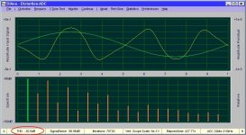
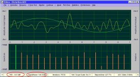
As it is not my intention to hijack this thread, I will not elaborate on this any further here, except showing two pictures. Fig. 1 shows one of original spectra and fig.2 shows the difference, where THD is "only" 50dB lower. This is because the spectrum is rather contaminated by noise, being the main limiting factor for this kind of measurements.
Cheers, E.
That only works when everything is perfectly correlated. It usually is not for distortion (never in my experiece). If the distortion contribution is small (-100 dB harmonics) and the loopback is not much better you won't get useful info.
[...]
That's a good point and you are quite right that -at least without rigorous precautions- the two distortion spectra will show a weak correlation. IOW, the difference between the two will be more or less meaningless.
BUT.... it can be done, though not easily, and that's precisely the reason why it took so long to get DiAna ready.
As it is not my intention to hijack this thread, I will not elaborate on this any further here, except showing two pictures. Fig. 1 shows one of original spectra and fig.2 shows the difference, where THD is "only" 50dB lower. This is because the spectrum is rather contaminated by noise, being the main limiting factor for this kind of measurements.
Cheers, E.
Attachments
Who else even uses the CMedia interfaces? The CMedia guys are great to work with but its a really small and slow moving market. They get a lot of the low end USB audio business but not high end, however its hard to justify making a chip for high end audio.
I think they are (or were) popular with PC OEMs. I have come across a few older PCI interfaces with their chips and a bunch of lower end USB stuff too.
I think Schiit and a few other "high end" manufacturers are using the CM6631A/CM6632A. It's a pretty good chip really, supports asynchronous and now 384kHz.
Try this. Start with everything off. Set your oscillator to 10 Hz max out. Connect it to a power amp. Connect that to a speaker. Turn the amp on. Then turn your oscillator on.
I met a guy who was tasked with designing fuse circuits for things like nuclear bombs. He told me the biggest stressor was being sure you could turn on the power. One mistake could have incredible consequences.
Sent from my SGH-M919 using Tapatalk
Holy Cow Demian, that isn't even funny. I wouldn't do that to my system.
I could though and put the input attenuators on their highest resistance.
I wouldn't want a big burst of what ever. And yes, now I understand.
Actually I was thinking everything was already on and turning the
dial down.
2nd - that would be a stressor indeed. I do recall some lessor stressors and
deadly on a smaller scale. Back in the old days they'd energize the heat seeker
on the aircraft missles and light a match and see if the seeker would track
the movement of moving the match left to right, up or down.
Once in a great while the missile would detonate of course not on the
same scale as a nuke. It would really suck if you were the guy testing
it...and it wouldn't matter which one it was for you...because you'd be gone.
But for everyone else....
Bob's oscillator and JFET operation
I have some questions about the leveler loop in Bob's oscillator and it's made me think of some other issues too.
Bob's oscillator integrates the loop level to smooth it and then compares this with a reference level.
Mathematically it should be equivalent to compare with the loop level with the reference level and then integrate the error to smooth it.
This would have the benefit that the capacitors should be very close to zero potential, easier to switch without leveler disturbance.
On Bob's oscillator this only saves a few resistors, maybe more important on a sweep tuned oscillator.
It seems that it would be easier to set the leveler loop, check for problems, any potential is an immediate clue.
Does that seem reasonable?
The related idea is to trim the oscillator feedback so that the JFET has essentially zero Gate-Source potential at nominal operation point.
That runs the risk of a small forward bias on the Gate.
At very low level there will be minimal forward conduction but I can find little information on use of a JFET in enhancement mode.
Any one have a link or experience?
One possibility is to use an actual depletion/enhancement mode MOSFET instead.
But I can't find one with a turn off threshold to equal the best JFETs.
Any recommendations?
David
The purpose of the integrator is to store the error so the differential amplifier output can go to zero. When the peak level is equal to the reference voltage this condition is met. With zero input the integrator doesn't undergo further change at it's output.
However the system has a ripple component so the output of the differential amplifier settles at the average of the peak to peak ripple. This ripple is seen at the Jfet gate.
The 10k resistor R15 in series with 100uf capacitor C6 allows the proportional error to pass through on a instantaneous basis. As the capacitor charges it replaces the proportional part with integral as the current through the resistor decreases.
At very low level there will be minimal forward conduction but I can find little information on use of a JFET in enhancement mode.
Any one have a link or experience?
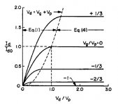
Here's a picture from Middlebrook circa 1963 showing that slight enhancement was always considered OK. In my experience 100-200mV does not cause any forward conduction except at extreme temperatures.
Attachments
Last edited:
Toshiba 2SK192A datasheet shows gate bias to +0.6v
That would be pushing things to the edge at hot temperatures, that's an RF device for use at 50 Ohmish resistances. The gate to source junction typically acts like an ordinary forward biased junction not much different than a bipolar transistor at 650 -700 mV it's full on conducting at room temperature.
...Glen made it clear that this was his idea of the cause of the problem. He asserted that the quadrature relationship of the SVF is never quite exactly 90 degrees and that the added phase shift from lower GBP op amps cured this problem...
I "set the Wayback machine to 6th of May 2012" to check on what Glen actually wrote >Here<
It's not obviously incorrect but it is odd.
The substitution of a faster op-amp will reduce the Q enhancement at hi frequency and that seems to have happened, as predicted by theory.
The odd bit is why his oscillator needed Q enhancement to function.
The Q enhancement seems to have coincidentally cancelled out low Q at hi frequency.
I don't understand why his amp had low Q at that frequency, it shouldn't be the op amps.
Perhaps lossy capacitors?
It is also a mystery why this comment was removed.
Perhaps it was accidental when he reformatted the site but I wonder if he found some problem and removed it deliberately.
I have sent him an e-mail but no response so far.
It has sparked a few new ideas.
Seems it should be possible to have an oscillator on the borderline of oscillation just by correct trim of the inverter and integrators.
Then the leveler loop has only to maintain the level, can be very heavily decoupled for ultra low distortion and noise.
Simple to implement and tune.
Here's a picture from Middlebrook circa 1963...
Toshiba 2SK192A datasheet shows gate bias to +0.6v
Thanks to you both. I hadn't seen either of these before.
Looks like I am OK to at least 100 mV and that's all I plan to use.
Best wishes
David
Last edited:
Seems it should be possible to have an oscillator on the borderline of oscillation just by correct trim of the inverter and integrators. Then the leveler loop has only to maintain the level, can be very heavily decoupled for ultra low distortion and noise.
Earlier implementations of my oscillator included a trim function which allowed to null the multiplier output. I removed this feature as the amount of multiplier decoupling is still limited by settling time requirements (finite multiplier authority is similar to slew-rate limiting in an amplifier).
Q enhancement has been very well studied in the literature on filter design. For the purpose of oscillator design adding the C in the inverter should be enough to prevent the leveling loop from saturating.
Samuel
Last edited:
Hi Samuel
It's always nice to have the benefit of your extensive experience.
Was your trim in the usual loop from the first integrator back to the inverter, or in the outer loop?
I just see it as a consequence of the Bode relations and clear from the Bode plot. But perhaps I miss some issues, any references?
It occurred to me yesterday that the separation of the leveler loop dynamics form the oscillator loop is very similar to the same problem in switch-mode power supplies.
There is a substantial literature on that, have you looked at any of it?
Best wishes
David
It's always nice to have the benefit of your extensive experience.
Earlier implementations of my oscillator included a trim function which allowed to null the multiplier output.
...finite multiplier authority is similar to slew-rate limit...
Was your trim in the usual loop from the first integrator back to the inverter, or in the outer loop?
Q enhancement has been very well studied in the literature
I just see it as a consequence of the Bode relations and clear from the Bode plot. But perhaps I miss some issues, any references?
It occurred to me yesterday that the separation of the leveler loop dynamics form the oscillator loop is very similar to the same problem in switch-mode power supplies.
There is a substantial literature on that, have you looked at any of it?
Best wishes
David
- Home
- Design & Build
- Equipment & Tools
- Low-distortion Audio-range Oscillator