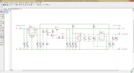
The problem seems to be the design around IC1 and S1. As far as I can see S1 can connect the output enable pin of IC1 to the supply. The problem is that the outputs of IC1 (ISO7230M) will be active when the enable pin is high OR is floating! The enable pin must be connected to ground to disable the outputs of IC1. So try to switch off S1 (or remove it) and connect pin 10 of IC1 to ground.
 it works directly with i2s also. another "tweak" for the ones using IC1
So, we can cut the S1 connection to pin 16 and hot wire it to pin 9 for S1 to work properly?

Also I got a sample ISO7640 from a friend and looks like it can replace the ISO7230.

Also I got a sample ISO7640 from a friend and looks like it can replace the ISO7230.
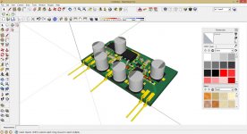
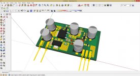
Not sure how useful these are but got the below pics from syllable while interacting over email... just sharing for others to have visbility..
K2MBOT_zps6e542cca.jpg Photo by rbalu72 | Photobucket
top2_zpsb11b1eab.jpg Photo by rbalu72 | Photobucket
K2MTOP2_zpsdc3a3c3a.jpg Photo by rbalu72 | Photobucket
PS : I am still gathering parts and yet to start assembling this dac.
K2MBOT_zps6e542cca.jpg Photo by rbalu72 | Photobucket
top2_zpsb11b1eab.jpg Photo by rbalu72 | Photobucket
K2MTOP2_zpsdc3a3c3a.jpg Photo by rbalu72 | Photobucket
PS : I am still gathering parts and yet to start assembling this dac.
Not sure how useful these are but got the below pics from syllable while interacting over email... just sharing for others to have visbility..
K2MBOT_zps6e542cca.jpg Photo by rbalu72 | Photobucket
top2_zpsb11b1eab.jpg Photo by rbalu72 | Photobucket
K2MTOP2_zpsdc3a3c3a.jpg Photo by rbalu72 | Photobucket
PS : I am still gathering parts and yet to start assembling this dac.
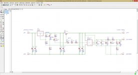
According to the discription on the zpsdc3a3c3a.jpg the I2s LR/DS1 and DA/DS2 connections need to be swaped (board silk screen error?).
TOP2_Zpsb11b1eab.jpg

Remove Lock and AM LED? Anything wrong there?
The S2 Red Boxed put to On state, why?
Can anyone explain?
So, we can cut the S1 connection to pin 16 and hot wire it to pin 9 for S1 to work properly?
Also I got a sample ISO7640 from a friend and looks like it can replace the ISO7230.
atupi tested the galvanic isolation and found out that the dac is working with S1 position on ON or OFF (with or without second 3.3V on IC1). Your mod should work (atupi proposed the same mod) but the lower pad should be grounded.
An externally hosted image should be here but it was not working when we last tested it.
According to the discription on the zpsdc3a3c3a.jpg the I2s LR/DS1 and DA/DS2 connections need to be swaped (board silk screen error?).
it seems so, but you can swap them without fear, the worst thing, you will not get lock.
all 4 working dacs (atupi's included) have the leds mounted and they are working with i2s and spdif ttl. Maybe it matters if you will use spdif 2 and 3 with arduino controler. the led pins are reconfigured to be used as spdif input, i don't have the chip datasheet but this is my understanding based on arduino's code (hifiduinos as syllabe deleted all the comments ....).Remove Lock and AM LED? Anything wrong there?
in order to be able to use spidif 2 and 3The S2 Red Boxed put to On state, why?
So, we can cut the S1 connection to pin 16 and hot wire it to pin 9 for S1 to work properly?
Also I got a sample ISO7640 from a friend and looks like it can replace the ISO7230.
Your schematic is very good. When you want to use the onboard spdif input pin 16 should be connected to pin 9 and if you want to use isolated I2S input pin 16 can be left floating (at least it worked for me).
Not sure how useful these are but got the below pics from syllable while interacting over email... just sharing for others to have visbility..
K2MBOT_zps6e542cca.jpg Photo by rbalu72 | Photobucket
top2_zpsb11b1eab.jpg Photo by rbalu72 | Photobucket
K2MTOP2_zpsdc3a3c3a.jpg Photo by rbalu72 | Photobucket
PS : I am still gathering parts and yet to start assembling this dac.
Syllable sent also to me these pictures but they should be used in combination with Arduino microcontroller otherwise forget about these changes.
Cmiu007 details are correct. We have built together 4 dacs and all of them are working very well. Next step is Arduino wich is on their way from China.
Last edited:
Syllable sent also to me these pictures but they should be used in combination with Arduino microcontroller otherwise forget about these changes.
Cmiu007 details are correct. We have built together 4 dacs and all of them are working very well. Next step is Arduino wich is on their way from China.
That's a positive message, I am moving slowly.
Thanks
I saw that site to,and wonder the same,they surley looks like they have the same maker..
Hi Ryssen
I have already in contact with him and ask me 250$ for assembled dual mono dac 9019k2m with one LCD. Isnt so much?
But ask 2-3 weeks after payment ....
I have already in contact with him and ask me 250$ for assembled dual mono dac 9019k2m with one LCD. Isnt so much?
But ask 2-3 weeks after payment ....
Expect poor support and no responsability crom him If anything goes wrong. At least this is my experience.
Hi Guys,
I want to try transformer IV for the 9018M2k using a pair of line input transformer 600:600 on this board, where can I tap into the +/- output and bypassing the opamp?
Thanks
I want to try transformer IV for the 9018M2k using a pair of line input transformer 600:600 on this board, where can I tap into the +/- output and bypassing the opamp?
Thanks
Hi Guys,
I want to try transformer IV for the 9018M2k using a pair of line input transformer 600:600 on this board, where can I tap into the +/- output and bypassing the opamp?
Thanks
How is your build? Fully functional?. I am yet to do mine.
Quan
Not yet,
Doing it a bit at a time, got some problem with the opamp so want to try transformer IV, signal locking from spdif is not much issue.
Doing it a bit at a time, got some problem with the opamp so want to try transformer IV, signal locking from spdif is not much issue.
Not yet,
Doing it a bit at a time, got some problem with the opamp so want to try transformer IV, signal locking from spdif is not much issue.
Thanks, i am follow with interest.
Quan
Hi,
Anyone know what the output impedance at the +/- output from the 9018M2K? Can I assume it to be 195R ? Same as the 9018 Bufallo DAC ?
Thanks
Anyone know what the output impedance at the +/- output from the 9018M2K? Can I assume it to be 195R ? Same as the 9018 Bufallo DAC ?
Thanks
Working on my own DAC (started last year):
- LiFePO4 powered
- Amanero USB to I2S module
- Raspberry I2S interface (needs add-on card for differential driving)
- SPFIF copper and fiber interfaces
- AES/EBU interface
- isolated SPI communication interface for micro/TFT
The shunt regulators for 1.2V and 3.3V and first routing DAC board (to change).
What do you think about the new AKM AK4495SEQ?
Attachments

- Status
- Not open for further replies.
- Home
- Source & Line
- Digital Line Level
- Low cost ES9018 Dac - Builders Thread