Hopefully it will emerge a platform lower priced than miniDSP. But still trustworty.
I’m not so negative though at the enverchar card combo.
I’m not so negative though at the enverchar card combo.
Thanks!High quality clock
Maybe a master clock driver and HF connector to sync other dacs or measure at some distance?
Guess half of hobby developers have the SPI USBi so nice to support that also.
I've started rough draft of the PCB. The biggest question I have is whether the USB MCU should be integrated on the board or just put a 20pin connector for York/Amanero module?
Pros and cons for two options:
1. MCU and ADAU on same board:
Pros:
One USB connector for multichannel audio input/output and ADAU configuration, no need in USBi. Easy to use board.
Cons:
Since the board would include MCU, the cost is going to be higher than just ADAU. However, overall it still cheaper than separate USBi + USB-I2S module
2. Place on the board for York/Amanero module
Pros:
Flexibility. If one already has Amanero and USBi - that would be better solution cost wise.
York still can be bought and placed on such board.
Cons:
No support, user is on his own for any troubleshooting
Price would be not optimal if one does not already have USBi/USB-I2S interface.
Maybe there is a middle ground: put USB MCU and place for separate module with 20 pin connector.
Just an illustration: the goal is basically to integrate these two PCBs into one module:
The USB interface would allow custom apps development:
Last edited:
I love the sigma software myself. So would not use any other to program ADAU
So I would need support for sigma studio.
Else I could just use a camilla dsp solution
So I would need support for sigma studio.
Else I could just use a camilla dsp solution
The draft looks something like this:

More pins will be added to the right side for all I2S in/outs
More pins will be added to the right side for all I2S in/outs
The main attraction for me about the nverchar solution is the low size and prize.
So I can buy two and put one in each speaker. Then all the cables can be inside the speaker.
The TDM to codec card makes syncronisity included for outputs.
I would off course wished for a output filter that did not distort, but a lot of the amp PWM card have their own input filter so only DC caps is mandatory

And on top of that, when a CS42448 codec card is added to the ADAU card and output filter is removed. I have 8 channels per speaker. That is mostly overkill so I then can balance the outputs on that card and still have 4 channels to play with.
Balancing reduses the noise of the output from regulators considerably. And almost all 2. order harmonics are removed when balancing if also the crap output caps are removed.
Providing the amp or balanse to unbalance cirquit have high CCMR of course.
So that solution is extreme low price FIR/IIR/SRC 96kHz good enough solution
A link to video on the crap cap distortion https://www.ti.com/video/series/precision-labs/ti-precision-labs-audio-fundamentals.html#
Trying out the AD1938 codec board with the opamps on it.
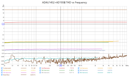
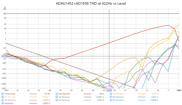
My friend bought the ADAU1452+AD1938 board for his project and encountered the same problem o fhigh THD level. Adjustment of any registry settings didn't help to solve the problem. Here are some pictures (more pictures in the attached pdf)
Attachments
Is it a tubeamp in the opamps🤣
Suspect the opamps on the AD1938 board are the reason, but i did not manage to remove one so haven't verified it.
Or maybe some cap in the filter that is built around it?
Suspect the opamps on the AD1938 board are the reason, but i did not manage to remove one so haven't verified it.
Or maybe some cap in the filter that is built around it?
Last edited:
On the DSP board that I have received ceramic SMD capacitors are soldered instead of SMD electrolytes o_0

Have you meassured it? Hopefully it is better.
I have the tiny caps, but bigger than on my CS42448 codec card
I have the tiny caps, but bigger than on my CS42448 codec card
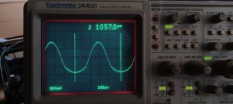
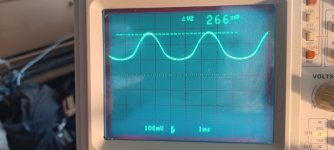
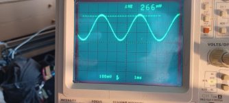
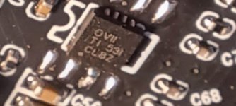
Interesting thing is that at the DAC outputs the sine waveform is fine. However, at the input of the opamp (red circle in the attached schematic) the waveform becomes distorted. The "OVII" marking is visible on the opamp. That is, opa1612 is used instead of opa2340.
Attachments
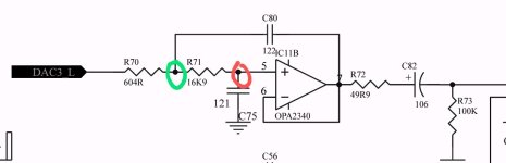
OPA1612 is not rail-to-rail opamp. What is the common mode in this circuit (DC offset at pin 5?) and opamp supply?
For OPA1612 allowed range is -V+2V to +V-2V:

For OPA2340 it is rail to rail:

For OPA1612 allowed range is -V+2V to +V-2V:
For OPA2340 it is rail to rail:
The power supply voltage for all operational amplifiers is the same 5.05 V. However, bias voltage at the pin 5 for input opamps is a bit lower (1.55V), than that for output opamps (1.77V).
That corresponds more with the codec spec: Each output pin has a nominal common-mode dc level of 1.5 V and swings ±1.27 V for a 0 dBFS digital input signal.
Think I must have destroyed mine codec when trying to remove one opamp
Think I must have destroyed mine codec when trying to remove one opamp
Is it possible to put extra DC on the codec output by adding digital DC on ADAU1452 output? Guess I can'tt check as the card probably is fried.
Says something in the spec about optional DC filter, but maybe we are lucky and it is off
Says something in the spec about optional DC filter, but maybe we are lucky and it is off
I'd say that it is better to replace the opamp with rail-to-rail one. With 1.27v input swing there is no way to make opa1612 work in specified region.
- Home
- Source & Line
- Digital Line Level
- low cost ADAU1452 China board...