Today I make up two of the AmyAlice kits I got from Dan. This was my first experience working with SMD, so I waited for a quiet time in the house. For soldering, I followed the advice given in this short video (
)
and I was delighted how smoothly it went. The key thing in the approach given in the video is to preload solder onto one of the pads (I believe Ixnay above did the same or similar), place the device, then bring the iron with a dab of fresh solder to that join, without jogging the device. This pins the device down, and it is straightforward after that. I had my iron set to 650°F and used Kester186 liquid solder applied through a tiny polypropylene tip (a type typically used in electrophoresis) and FireMetal solder (the very fine gauge is helpful). I used a smallish screwdriver tip (Weller ETB 3/32”) that I have been using for a while, and it worked well here too.
Here is my workspace just before starting. I found it helpful to tape the board down rather than use clips/helping hands, and to lay out and label the unfamiliar components. After some head scratching trying to figure out the diode, I finally looked under magnification and found the cathode mark (3 very fine lines). The other components were more straightforward.

Here is my first board after all the SMDs were soldered and cleaned up. I'm not sure why I decided to completely fill the large pads with solder; I was probably channeling my childhood art class training...

Dan’s choice of white makes a very handsome PCB, no?
After installing the large caps, I inspected the board under magnification to check my soldering. I also double checked things by applying 24VDC to the inputs and, with no load, checking voltages around the board. I got the expected values (either the supply voltage or ground) in the places where the schematic indicated they should be.
Next step is the enclosure; I have some LeMotech 3.9”x2.4”x1.0” boxes and some cable glands ready to go.
Thanks again to Dan for making it so easy for many of us to implement Mark Johnson’s gift of a great filter.
and I was delighted how smoothly it went. The key thing in the approach given in the video is to preload solder onto one of the pads (I believe Ixnay above did the same or similar), place the device, then bring the iron with a dab of fresh solder to that join, without jogging the device. This pins the device down, and it is straightforward after that. I had my iron set to 650°F and used Kester186 liquid solder applied through a tiny polypropylene tip (a type typically used in electrophoresis) and FireMetal solder (the very fine gauge is helpful). I used a smallish screwdriver tip (Weller ETB 3/32”) that I have been using for a while, and it worked well here too.
Here is my workspace just before starting. I found it helpful to tape the board down rather than use clips/helping hands, and to lay out and label the unfamiliar components. After some head scratching trying to figure out the diode, I finally looked under magnification and found the cathode mark (3 very fine lines). The other components were more straightforward.
Here is my first board after all the SMDs were soldered and cleaned up. I'm not sure why I decided to completely fill the large pads with solder; I was probably channeling my childhood art class training...
Dan’s choice of white makes a very handsome PCB, no?
After installing the large caps, I inspected the board under magnification to check my soldering. I also double checked things by applying 24VDC to the inputs and, with no load, checking voltages around the board. I got the expected values (either the supply voltage or ground) in the places where the schematic indicated they should be.
Next step is the enclosure; I have some LeMotech 3.9”x2.4”x1.0” boxes and some cable glands ready to go.
Thanks again to Dan for making it so easy for many of us to implement Mark Johnson’s gift of a great filter.

Looks really good @northpaw !
I like the white boards as well and chose it specifically as I find it helpful with SMD soldering as it highlights the solder, pads, flux, and components when doing the Quality Assurance (QA) checks. It looks pretty nice all cleaned up and finished up as well. The 2mm boards with ENIG gold finish are super nice. I wish I could afford that with all the PCBs I buy.
Nice work!
birdbox,
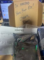
The YIWDAF4 kit arrived safely. I love the BOM on the front and that everything is already marked taking the guesswork out of trying to determine parts value.
Now I just need to find time to build the F4 and YIWDAF4.
The YIWDAF4 kit arrived safely. I love the BOM on the front and that everything is already marked taking the guesswork out of trying to determine parts value.
Now I just need to find time to build the F4 and YIWDAF4.
Hey @birdbox,
I received my kits the other day and put the SoftHeat together. Nice board and pretty hard to mess up the assembly with the parts checklist right on the bag! I'm actually waiting for that same cool blue soldering station in the post above to show up today before I do any more work. 😀 Thanks for the note in the package warning me of the itty bitty SMD parts. I seriously need warnings like that or I'd be on the floor picking bits out of the carpet after I ripped it open and sent everything flying. 🤣
I received my kits the other day and put the SoftHeat together. Nice board and pretty hard to mess up the assembly with the parts checklist right on the bag! I'm actually waiting for that same cool blue soldering station in the post above to show up today before I do any more work. 😀 Thanks for the note in the package warning me of the itty bitty SMD parts. I seriously need warnings like that or I'd be on the floor picking bits out of the carpet after I ripped it open and sent everything flying. 🤣
I now have 10 full H9KPXG kits if anyone wants one. I'll update the first post in the next day or two, but I am mentioning it here to bump up the post for awareness. PM me if you'd like a full kit for Mark's soft start H9KPXG.
Here is the board all populated.

Here is the board all populated.
I just took delivery of a set of AmyAlice full kits. They travelled safe and sound to Toronto, Canada in just a couple of days.
Dan deserves full marks for making these available and for expediting their delivery. Thanks.
Dan deserves full marks for making these available and for expediting their delivery. Thanks.
Made up 20 Cheapomodo kits (design by Mark Johnson) if anyone will benefit from having a premade kit all ready to build up. See updated first post for details.

Last edited:
DM (Birdbox / Dan) or ask him to DM you here first. He is SUPER to work with (multiple times now)!!! Great communication, kit quality, prices and prompt deliveries!!!
Package is already with post office on its way to @ppt1956 🛩️ Superfast.... Under 2 hours. New personal best 
Last edited:
I built up a number of Mark Johnson's VRDN kits a couple weeks back. They are just PCB and parts kits. The picture below shows one after being fully populated for reference.
I'm keeping a few for myself and happy to share the remaining kits with fellow diy-ers. Reference updated 1st post.

I'm keeping a few for myself and happy to share the remaining kits with fellow diy-ers. Reference updated 1st post.
Last edited:
VRDN kits arrived today, fast shipping as usual. Thanks for making these kits available. 