Can you show a picture of this baffle / speaker design?
I think your first steps should be learning about baffle step loss, and taking speaker measurements.
I think your first steps should be learning about baffle step loss, and taking speaker measurements.
Overall concept is solid. I would reduce mid driver to 4" or even good 3" for better off-axis response.I've not purchased drivers, so really anything is on the table. However, these 3 are what I'm currently focused on.
However, the drivers themselves make me slighly mad. How come that ancient mass-produced Soviet 5" mid-woofer is wastly more linear than new SB Acoustics offering, backed by decades of research and (supposedly) hundreds of FEM simulations? In a suboptimal enclosure, no less.
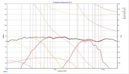
Note the 2 dB per division scale. Even that 5.5 khz peak is not from the driver itself, but from the plastic decorative baffe.

Please have a good read of this thread: https://www.diyaudio.com/community/...-design-your-own-speaker-from-scratch.332688/
Besides individual driver phase (in XSim on the Frequency Graph, click "Curves", then select each driver displayed and check the "show with phase curve" box and uncheck it for the System curve), we also need to see each driver response to know what the xo points and xo slopes look like and if they are appropriate or not for the drivers chosen.
For phase to be accurate, you also need to include the relative acoustic centers for each driver, which at best is a guestimate in the simulation phase based on the actual physical location of the voice coil and cone attachment point as seen in the spec sheet drawings (enlarge to real size on your computer screen and then take a physical measurement) and based on the location of the drivers on the baffle. This almost deserves its own small tutorial. Include these figures in "mod delay" under "Tune" for each driver. Your goal is to achieve good phase alignment between drivers at least an octave or so above and below their xo points (depends on the steepness of the xo slopes and therefore the range of frequency overlap).
I would suggest 2nd order acoustic slopes which should be achievable with 2nd order electrical filters, with perhaps the tweeter only needing 3rd order electric in order to get good tweeter/mid phase matching (tweeter polarity may need reversing). Second order acoustic can even sometimes be achieved with just single order electrical when you also take into account the natural roll-off of the driver. Third order everywhere is probably unnecessary and just creating layout problems for you besides costing you too much cash. As a rule of thumb, simple is generally better whenever possible.
As a novice, you should also use xo target slopes for each driver and then shape your responses to match as best you can. I cannot overstate how helpful this can be when you are just starting out. In XSim, there a couple of ways to do this - I used Response Modeler to create the target curves and then import into XSim (you'll need Excel for that though). Agian this could be a whole separate tutorial.
Are you unable to find the correct cap values needed in every single case with just a single capacitor?
Although it's always less accurate, you can do a sim that accounts for baffle step loss without including it in your curves by targeting a downward tilting summed response so that the LF's are about 5 or 6 dB louder than the HF's in your sim (that assumes a flat response as your goal when BSC is included) but that is still not the best way to go for sims (both box effects and baffle effects should be added to each of your drivers' frd and zma files - with the tweeter zma being the only exception - to ensure any real level of accuracy) and sims should be followed up with real world measurements in any case. Here in your sim, without BSC included you have achieved an upward tilting response so the result when placed away from walls (ie with a 6dB baffle step loss in the LF's included) is likely to be a very, very bright sounding speaker with a touch too much honkiness right in the middle of the midrange (that can depend on baffle width though).
Based on the responses I've gotten, it's obvious I have a lot to learn about everything.Can you show a picture of this baffle / speaker design?
I think your first steps should be learning about baffle step loss, and taking speaker measurements.
I'd rather not share as as everything I've seen that would be close to what I want to do has been negative. "Won't work", "Can't Work", "Waste of time", etc... I'd rather not go down that trail and just work it up and learn for myself that it won't work.
Lots to take in here, but I've attached the FR chart with phase shown (I think). As for your question about the caps, I spent a lot of time searching for single caps and wasn't able to find the necessary values. Since I've redesigned it about 5 times, I'm not going to spend a lot of time doing that again. Once I'm confident that I'm ready to purchase, I'll do some trade off study's on cost versus accuracy and see if single caps can be "close enough".Please have a good read of this thread: https://www.diyaudio.com/community/...-design-your-own-speaker-from-scratch.332688/
Besides individual driver phase (in XSim on the Frequency Graph, click "Curves", then select each driver displayed and check the "show with phase curve" box and uncheck it for the System curve), we also need to see each driver response to know what the xo points and xo slopes look like and if they are appropriate or not for the drivers chosen.
For phase to be accurate, you also need to include the relative acoustic centers for each driver, which at best is a guestimate in the simulation phase based on the actual physical location of the voice coil and cone attachment point as seen in the spec sheet drawings (enlarge to real size on your computer screen and then take a physical measurement) and based on the location of the drivers on the baffle. This almost deserves its own small tutorial. Include these figures in "mod delay" under "Tune" for each driver. Your goal is to achieve good phase alignment between drivers at least an octave or so above and below their xo points (depends on the steepness of the xo slopes and therefore the range of frequency overlap).
I would suggest 2nd order acoustic slopes which should be achievable with 2nd order electrical filters, with perhaps the tweeter only needing 3rd order electric in order to get good tweeter/mid phase matching (tweeter polarity may need reversing). Second order acoustic can even sometimes be achieved with just single order electrical when you also take into account the natural roll-off of the driver. Third order everywhere is probably unnecessary and just creating layout problems for you besides costing you too much cash. As a rule of thumb, simple is generally better whenever possible.
As a novice, you should also use xo target slopes for each driver and then shape your responses to match as best you can. I cannot overstate how helpful this can be when you are just starting out. In XSim, there a couple of ways to do this - I used Response Modeler to create the target curves and then import into XSim (you'll need Excel for that though). Agian this could be a whole separate tutorial.
Are you unable to find the correct cap values needed in every single case with just a single capacitor?
Although it's always less accurate, you can do a sim that accounts for baffle step loss without including it in your curves by targeting a downward tilting summed response so that the LF's are about 5 or 6 dB louder than the HF's in your sim (that assumes a flat response as your goal when BSC is included) but that is still not the best way to go for sims (both box effects and baffle effects should be added to each of your drivers' frd and zma files - with the tweeter zma being the only exception - to ensure any real level of accuracy) and sims should be followed up with real world measurements in any case. Here in your sim, without BSC included you have achieved an upward tilting response so the result when placed away from walls (ie with a 6dB baffle step loss in the LF's included) is likely to be a very, very bright sounding speaker with a touch too much honkiness right in the middle of the midrange (that can depend on baffle width though).
Attachments
If you don't want to be put off by dispiriting criticism, that's fine, but it also means you won't be gaining any good feedback, either.Based on the responses I've gotten, it's obvious I have a lot to learn about everything.
I'd rather not share as as everything I've seen that would be close to what I want to do has been negative. "Won't work", "Can't Work", "Waste of time", etc... I'd rather not go down that trail and just work it up and learn for myself that it won't work.
Virtually all these XO sims are not going to be useful to you without taking acoustic aspects like baffle response, box modeling, diffraction and off-axis measurements into consideration.
At the least you could include the 6dB step by sight.I've not included a baffle as I really have no idea how to do it.
Here is where to find the phase option..
Virtually all these XO sims are not going to be useful to you without taking acoustic aspects like baffle response, box modeling, diffraction and off-axis measurements into consideration.
Just got to so disagree with this statement. Every time someone is working up a xo regardless of whether or not the files are accurate, you are learning how to use XSim and how to design a xo from scratch. That is extremely worthwhile for a beginner.
Looking at the new Response graph:
- use different colors for each driver's response. You can select them in the curve" drop down menu. Better yet always choose the same colors for the drivers, it'll make it easier to read each time.
- yes, you have the correct phase now displayed but it shows that the phase alignment in the 2 xo regions is not too good. They should overlap, line up together, etc, around the xo frequencies, such that when you reverse the polarity on the mid, you should get wide and deep nulls in the summed response at the xo points. As a learning exercise, change your xo electrical order, change some values and/or change the mod delay and observe the results on phase.
- Those aren't terrible xo frequency choices but I think the mid/tweeter and perhaps the mid/woofer xo's are too high. That's a robust tweeter so it can handle a lower xo frequency and that's good because you want to stay away from that rising breakup that you get with that mid starting at about 4kHz. Keep it much lower in SPL in other words. I'd select a xo point closer to 2000-2500Hz and a lower point closer to 300-400Hz.
Thanks, I'll continue to mess around with it. Do you have a FR curve showing "good" phase so that I have something to shoot for?Just got to so disagree with this statement. Every time someone is working up a xo regardless of whether or not the files are accurate, you are learning how to use XSim and how to design a xo from scratch. That is extremely worthwhile for a beginner.
Looking at the new Response graph:
- use different colors for each driver's response. You can select them in the curve" drop down menu. Better yet always choose the same colors for the drivers, it'll make it easier to read each time.
- yes, you have the correct phase now displayed but it shows that the phase alignment in the 2 xo regions is not too good. They should overlap, line up together, etc, around the xo frequencies, such that when you reverse the polarity on the mid, you should get wide and deep nulls in the summed response at the xo points. As a learning exercise, change your xo electrical order, change some values and/or change the mod delay and observe the results on phase.
- Those aren't terrible xo frequency choices but I think the mid/tweeter and perhaps the mid/woofer xo's are too high. That's a robust tweeter so it can handle a lower xo frequency and that's good because you want to stay away from that rising breakup that you get with that mid starting at about 4kHz. Keep it much lower in SPL in other words. I'd select a xo point closer to 2000-2500Hz and a lower point closer to 300-400Hz.
The first thing I ask people... what system sensitivity are you targeting?
You have chosen an 88dB sensitive woofer. if using this nearfield, or hard up against the wall, very little bafflestep compensation will be neeed.
If however (as I suspect) you are using these in a normal listening environment, a few feet away from the front wall (for serious listening), then these will sound thin.
You want to be targetting ~ 84dB sensitivity (allowing ~4dB bafflestep compensation).
The reason this is important, is your whole crossover will change.
If you are going to spend this much money on good drivers, then I recommend you hold off buying crossover parts and instead by a measurement microphone and build a test box. that way you'll have real /hard measurement data and make a much better first design attempt. (and save money on not used crossover parts).
Re midrange choice. If the NRX is not preferred by some - then the MR13 or MW13TX (textreme) if you want to keep an all satori combination.
There are numerous SBA / Satori designs out there. Another option is to pick a driver combo, should you not get a crossover you like, you can forklift an existing design that should be good.
Okay, I downloaded the response modeler. I must say it's a bit intimidating. If I understand correctly, one goal is to take my existing FRD/ZMA files and modify with the baffle effects based on my enclosure design. I then import back into xSIM to see the impact on the system and (If necessary) modify to get decent FR and phase plots. Is that correct?Please have a good read of this thread: https://www.diyaudio.com/community/...-design-your-own-speaker-from-scratch.332688/
Besides individual driver phase (in XSim on the Frequency Graph, click "Curves", then select each driver displayed and check the "show with phase curve" box and uncheck it for the System curve), we also need to see each driver response to know what the xo points and xo slopes look like and if they are appropriate or not for the drivers chosen.
For phase to be accurate, you also need to include the relative acoustic centers for each driver, which at best is a guestimate in the simulation phase based on the actual physical location of the voice coil and cone attachment point as seen in the spec sheet drawings (enlarge to real size on your computer screen and then take a physical measurement) and based on the location of the drivers on the baffle. This almost deserves its own small tutorial. Include these figures in "mod delay" under "Tune" for each driver. Your goal is to achieve good phase alignment between drivers at least an octave or so above and below their xo points (depends on the steepness of the xo slopes and therefore the range of frequency overlap).
I would suggest 2nd order acoustic slopes which should be achievable with 2nd order electrical filters, with perhaps the tweeter only needing 3rd order electric in order to get good tweeter/mid phase matching (tweeter polarity may need reversing). Second order acoustic can even sometimes be achieved with just single order electrical when you also take into account the natural roll-off of the driver. Third order everywhere is probably unnecessary and just creating layout problems for you besides costing you too much cash. As a rule of thumb, simple is generally better whenever possible.
As a novice, you should also use xo target slopes for each driver and then shape your responses to match as best you can. I cannot overstate how helpful this can be when you are just starting out. In XSim, there a couple of ways to do this - I used Response Modeler to create the target curves and then import into XSim (you'll need Excel for that though). Agian this could be a whole separate tutorial.
Are you unable to find the correct cap values needed in every single case with just a single capacitor?
Although it's always less accurate, you can do a sim that accounts for baffle step loss without including it in your curves by targeting a downward tilting summed response so that the LF's are about 5 or 6 dB louder than the HF's in your sim (that assumes a flat response as your goal when BSC is included) but that is still not the best way to go for sims (both box effects and baffle effects should be added to each of your drivers' frd and zma files - with the tweeter zma being the only exception - to ensure any real level of accuracy) and sims should be followed up with real world measurements in any case. Here in your sim, without BSC included you have achieved an upward tilting response so the result when placed away from walls (ie with a 6dB baffle step loss in the LF's included) is likely to be a very, very bright sounding speaker with a touch too much honkiness right in the middle of the midrange (that can depend on baffle width though).
My problem is that my baffle isn't able to be modeled with the standard rectangular speaker box. I didn't see an option for significantly changing the baffle. Did I miss it or is the standard speaker box the only real option?
While this isn't my speaker design, I worked 40 years in the defense industry and have a passion for military aircraft. As such, I could imagine wanting to make a speaker enclosure that borrows from the F117 stealth fighter. Think of a front baffle full of facets mimicking those of the stealth bomber. Could that be modeled with this tool (or any other tool for that matter)? If not, is the only real option to get really good FR/Phase curves without the baffle impacts and then build, listen, and adjust based on what you're hearing? Probably a real stretch for an old deaf guy, but something I may try anyway (However, to this point I'm not getting great FR/Phase results....I'm not sure why, but I'll keep trying).
What you say makes a lot of sense. I've not bought any crossover parts and figured I'd wait until I was really confident in the design before going forward. As for sensitivity, I was shooting for around 88. Why? Only because I was using the Salk SS9.5 as my target (Not the enclosure design, but drivers, sensitivity and FR). It uses the woofer & tweeter I've selected, but uses an AudioTechnology midrange. I don't know which AudioTechnology midrange Salk uses and gave up looking. I'm certainly not tied to the SB15NRX, but would like a midrange that has the potential to be very good.The first thing I ask people... what system sensitivity are you targeting?
You have chosen an 88dB sensitive woofer. if using this nearfield, or hard up against the wall, very little bafflestep compensation will be neeed.
If however (as I suspect) you are using these in a normal listening environment, a few feet away from the front wall (for serious listening), then these will sound thin.
You want to be targetting ~ 84dB sensitivity (allowing ~4dB bafflestep compensation).
The reason this is important, is your whole crossover will change.
If you are going to spend this much money on good drivers, then I recommend you hold off buying crossover parts and instead by a measurement microphone and build a test box. that way you'll have real /hard measurement data and make a much better first design attempt. (and save money on not used crossover parts).
Re midrange choice. If the NRX is not preferred by some - then the MR13 or MW13TX (textreme) if you want to keep an all satori combination.
There are numerous SBA / Satori designs out there. Another option is to pick a driver combo, should you not get a crossover you like, you can forklift an existing design that should be good.
I'll probably take your advice on the test box. That's kind of what started my journey anyway. I was looking for a wood working project and came up with the box design after watching a few hundred YouTube videos on various wood working items (None of them were speakers). Of course I don't know how to go about testing, but I'm sure there are plenty of resources on here and other internet sites to help me out.
@jReave I didn't say learning Xsim is not worthwhile; I just think a bunch of time trying to perfect datasheet derived XOs as proof of concept for this project - even more so if the front plane isn't rectangular - isn't delivering much. Like Dave said, there are lots of SB/Satori designs and XO schematics out there to lean on. It doesn't need validation.
@Dfairc777 Try The Edge - you can drag and drop baffle edges into unusual shapes and see a basic diffraction response.
I'd urge you to reconsider not sharing a sketch of the front plane of your F-117 inspired concept.
@Dfairc777 Try The Edge - you can drag and drop baffle edges into unusual shapes and see a basic diffraction response.
I'd urge you to reconsider not sharing a sketch of the front plane of your F-117 inspired concept.
Unless Jim Salk uses a special order WO24P woofer (with shorter voice coil or other changes to increase sensitivity), I'd wager he either hasn't applied as much BSC as most DIY designs would, or possibly over stating the sensitivity, as it is a commercial design and 87 whatevers must be better than 86 whatevers to the laypersonWhat you say makes a lot of sense. I've not bought any crossover parts and figured I'd wait until I was really confident in the design before going forward. As for sensitivity, I was shooting for around 88. Why? Only because I was using the Salk SS9.5 as my target (Not the enclosure design, but drivers, sensitivity and FR). It uses the woofer & tweeter I've selected, but uses an AudioTechnology midrange. I don't know which AudioTechnology midrange Salk uses and gave up looking. I'm certainly not tied to the SB15NRX, but would like a midrange that has the potential to be very good.
I'll probably take your advice on the test box. That's kind of what started my journey anyway. I was looking for a wood working project and came up with the box design after watching a few hundred YouTube videos on various wood working items (None of them were speakers). Of course I don't know how to go about testing, but I'm sure there are plenty of resources on here and other internet sites to help me out.
You might be right about Salk.Unless Jim Salk uses a special order WO24P woofer (with shorter voice coil or other changes to increase sensitivity), I'd wager he either hasn't applied as much BSC as most DIY designs would, or possibly over stating the sensitivity, as it is a commercial design and 87 whatevers must be better than 86 whatevers to the layperson
I'm not doing the F-117, but thought it was a good example. I'm really thinking my best bet is to select the 3 drivers and build the enclosure. If it comes out well, I'll share before testing. While I know nothing about testing, it seems to me that would be a much more accurate way of approaching. I guess the risk is that it tests so bad that no crossover can fix it, but that's not a big deal. My shop is littered with stuff I started to build and then scrapped.@jReave I didn't say learning Xsim is not worthwhile; I just think a bunch of time trying to perfect datasheet derived XOs as proof of concept for this project - even more so if the front plane isn't rectangular - isn't delivering much. Like Dave said, there are lots of SB/Satori designs and XO schematics out there to lean on. It doesn't need validation.
@Dfairc777 Try The Edge - you can drag and drop baffle edges into unusual shapes and see a basic diffraction response.
I'd urge you to reconsider not sharing a sketch of the front plane of your F-117 inspired concept.
For reference, here's an open crossover schematic for Troels' Seas 3 Way classic MK1 .
A more recent (but closed schematic) variant is the 941 - he uses the WO24P + MR13P + a Beryllium SB tweeter on a stepped baffle. There's also a newer Textrene 5" that you can search on here.
All these drivers can be sold on or used in any number of projects.
A thread on measurement is here https://www.audiosciencereview.com/...ents-spinoramas-with-rew-and-vituixcad.21860/
Some video courses on speaker design + measurements that I saw recommended are https://audiojudgement.com/courses.html
I think they run promotions at certain times + one can apply coupons off the list price
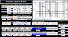
Here's an 3-way example with decent phase alignment in the xo regions (3 graphs presented for clarity):
Woofer/Mid (quite excellent alignment both above and below the xo frequency):

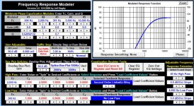
Mid/Tweeter (very good above the xo frequency; not quite as good below):

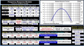
Mid with Reverse Polarity:

Sim is with spec sheet responses using the SB WO24P-8, Satori MW16P-8 and the SB 29SDAC with all baffle and box effects included. Electrically, the tweeter is 3rd order with everything else 2nd order, plus a few little eq and phase adjustment filters as well.
Woofer/Mid (quite excellent alignment both above and below the xo frequency):
Mid/Tweeter (very good above the xo frequency; not quite as good below):
Mid with Reverse Polarity:
Sim is with spec sheet responses using the SB WO24P-8, Satori MW16P-8 and the SB 29SDAC with all baffle and box effects included. Electrically, the tweeter is 3rd order with everything else 2nd order, plus a few little eq and phase adjustment filters as well.
Attachments

For Dave Bullet, here's a little trick that can sometimes work to gain you a couple dB of sensitivity in a 3-way:
Here's the SB WO24P-8 in a 3-way sim. Grey is the raw response with box and baffle effects included and blue is what you get when you add in the xo filter. Granted this is just a sim with spec sheet info and not with measurements, but my expectation is that this is probably what's happening with the Salk speaker.

- tune the woofer box response so you are quite flat right to the roll-off or even with a little boost right before it
- now when you insert the woofer filter and you happen to get a couple of dB boost right before the roll-off due to the interaction of the filter and the driver's impedance peaks (doesn't happen with every driver and can certainly depend on your chosen xo frequency), you don't need to compensate for it but instead can use it to raise the overall sensitivity of the design and to create a more gradual LF roll-off at the same time (which is usually more desirable but that can depend on room size and speaker placement).
Here's the SB WO24P-8 in a 3-way sim. Grey is the raw response with box and baffle effects included and blue is what you get when you add in the xo filter. Granted this is just a sim with spec sheet info and not with measurements, but my expectation is that this is probably what's happening with the Salk speaker.
Yes, the program is loaded with utility that can overwhelm at first but unfortunately the diffraction modeling doesn't allow for very complex designs. Like motokok suggested, the Edge offers more flexibility with shapes but ironically doesn't allow for edge modifications. So you might try the baffle diffraction module in VituixCAD which allows for both. It's another quite intimidating program for beginners though but you have the option of just using that particular model and nothing else.Okay, I downloaded the response modeler. I must say it's a bit intimidating.
Response Modeler does however also offer box impedance manipulation which is often overlooked in the process. The upper left EQ module along with the User Adjustable baffle effects module can also be very useful for adjusting for different speaker placement options.
For target filter creation, use the High Pass and Low Pass functions in the upper box. First make sure that both the FRD Data and EQ Response modules are clear such that you have a single flat line in the Modeled Response Function graph. Then you do something similar to the pics below for a 3-way, saving the responses each time. Then in XSim, create 3 other new drivers that remain electrically unattached to anything and then import the target filters as those drivers' frequency responses. Lastly, display them in XSim by selecting the 'driver only' option under 'Curves".
Given your goals, I wonder if you might be able to achieve both your aesthetic preferences and minimize baffle edge effects with a design something along the lines of speakers by Avalon.
Attachments
- Home
- Loudspeakers
- Multi-Way
- Looking for opinions on my first passive crossover