Well, the offer still stands... 🙂
Re: glowing triodes, if that is a hard condition, I may need to attach some plutonium on the top. It glows red on its own so it will look nice in the dark.
Re: glowing triodes, if that is a hard condition, I may need to attach some plutonium on the top. It glows red on its own so it will look nice in the dark.
Last edited:
I am one of SIT people too. No SIT people should be scared of the GM100, we love them cute triodes instead.
Only a sissy would use little tubes like that. Now an RCA 4-1000 ... that's a tube!
My lasercutting machine had six of them, way back in the 1980s, and they handle 7000 volts. To tune this thing I needed a metre of PVC conduit with a spanner pushed into the end of it, because the arcs would jump about 500 mm if you got too close. It ran at 40kV and half an amp, and I only know of one guy who got zapped and survived it. He was thrown about ten metres into a wall and couldn't recall his own name for days afterwards.
Now that winter is here, I need a new room heater, so I'm back to working on making this transformer coupled amp a reality.
I have received my output transformers from J&K Audio Design, and they are huge - about 15.5 lbs. each. A while ago, I also acquired some Tokin 2SK182ES SITs, so my plan is to use them as output devices.
My latest idea is to do away with bias supplies and use self bias for both the voltage amplifier stage and the source follower output stage. I've simulated this in LTSpice and it appears to be doable. I have also built a voltage amplifer test jig using the 2SJ28 VFET and have performed some measurements, so things are actually moving along.
Attachments

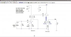

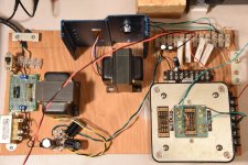
I assembled a circuit to test the 2SJ28 voltage amp loaded with the interstage transformer. The Magnequest RIT-5 interstage (5k:5k) is gapped for 20mA current and is rated at greater than 50H. In my toob daze, it was used with a 5842 triode (plate resistance of about 1600 ohms) to drive a 2A3 or 45 directly heated triode output tube. I think I bought this transformer sometime in the early 1990s.
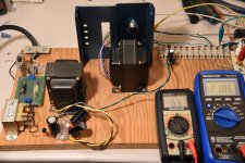
The test rig was built with parts that I had lying around. I ended up with a 120VAC:120VAC transformer, rectified, and filtered with CLC. I used a variac to dial in the voltage to the 2SJ28. Vds ended up at about 142V with Iq of 18mA.
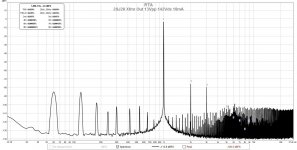
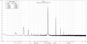
Distortion numbers were consistent with my previous Hammond choke loaded Sony VFET voltage amp implementations. I checked the frequency response using my HP oscillator and oscilloscope. Response was flat from 20Hz to 40kHz (1.14Vpp in / 14.8Vpp out), dropped slightly (14.6Vpp) to 60kHz, and dropped to 14.4Vpp at 100kHz. No frequency peaks or dips were observed.
I put the test rig together without checking or adjusting for hum and noise and this shows in the FFT results.
The test rig was built with parts that I had lying around. I ended up with a 120VAC:120VAC transformer, rectified, and filtered with CLC. I used a variac to dial in the voltage to the 2SJ28. Vds ended up at about 142V with Iq of 18mA.
Distortion numbers were consistent with my previous Hammond choke loaded Sony VFET voltage amp implementations. I checked the frequency response using my HP oscillator and oscilloscope. Response was flat from 20Hz to 40kHz (1.14Vpp in / 14.8Vpp out), dropped slightly (14.6Vpp) to 60kHz, and dropped to 14.4Vpp at 100kHz. No frequency peaks or dips were observed.
I put the test rig together without checking or adjusting for hum and noise and this shows in the FFT results.
Attachments

humm is some time that I dont play with tube but having too 5k:5K gapped at 30ma for a 10y and psu 225v with gz34 if I mod for choke input can I have 120v maybe ? spare sony too ,can I use for FE in sony kit2 ??I assembled a circuit to test the 2SJ28 voltage amp loaded with the interstage transformer. The Magnequest RIT-5 interstage (5k:5k) is gapped for 20mA current and is rated at greater than 50H. In my toob daze, it was used with a 5842 triode (plate resistance of about 1600 ohms) to drive a 2A3 or 45 directly heated triode output tube. I think I bought this transformer sometime in the early 1990s.
The test rig was built with parts that I had lying around. I ended up with a 120VAC:120VAC transformer, rectified, and filtered with CLC. I used a variac to dial in the voltage to the 2SJ28. Vds ended up at about 142V with Iq of 18mA.
Distortion numbers were consistent with my previous Hammond choke loaded Sony VFET voltage amp implementations. I checked the frequency response using my HP oscillator and oscilloscope. Response was flat from 20Hz to 40kHz (1.14Vpp in / 14.8Vpp out), dropped slightly (14.6Vpp) to 60kHz, and dropped to 14.4Vpp at 100kHz. No frequency peaks or dips were observed.
I put the test rig together without checking or adjusting for hum and noise and this shows in the FFT results.
thank for helps
I have looked into a tube driver that certainly is not for the sissies.
And that runs on a LOW LOW Vb, so no extra power supply is needed.
As well, the filament can be used as for auto-bias. . .
Now how can it be more simple?

OK the folding is simple PNP just for demo.
BAD BAD - it has a capacitor. So forget it.
And that runs on a LOW LOW Vb, so no extra power supply is needed.
As well, the filament can be used as for auto-bias. . .
Now how can it be more simple?
OK the folding is simple PNP just for demo.
BAD BAD - it has a capacitor. So forget it.
Attachments
I remember all you that MOSFET's has a much bigger input capacitance than tubes and this is amplified thanks to the well known Miller Effect. And a capacitance toguether to a transformer inductance is a temptation to start it to oscillate. And if oscillation's amplitude are high, the tiny MOSFET's gate insulation may be damaged.
I would just try using an extra RC filter at the VFET for decoupling and drop the voltage to what you want. If you use source resistor bias and account for the voltage drop across the transformer, that may add up to 30V. If you use a Vds of 140V, then you're up to a supply voltage of 170V. A RC filter with a couple of thousand ohms will get you there. You can also try a higher voltage operating point.humm is some time that I dont play with tube but having too 5k:5K gapped at 30ma for a 10y and psu 225v with gz34 if I mod for choke input can I have 120v maybe ? spare sony too ,can I use for FE in sony kit2 ??
thank for helps
Anyways, the circuit doesn't have many parts, so it's easy to set up and test. I find doing research and simulations are useful, but testing out ideas for real is the best. I remember, a few years ago, I first started thinking about inductor loading VFET voltage amps. After doing some LTSpice simulations, I wanted to get a "real" audio choke so I emailed a tube transformer winder to ask about getting a pair made. He insisted that I was wasting my time using inductors for that purpose, so I ended up buying some cheap Hammond chokes to try instead. And luckily, they worked nicely. So, I believe in experimenting; no matter the results, I always learn something.
luminaria onesI would just try using an extra RC filter at the VFET for decoupling and drop the voltage to what you want. If you use source resistor bias and account for the voltage drop across the transformer, that may add up to 30V. If you use a Vds of 140V, then you're up to a supply voltage of 170V. A RC filter with a couple of thousand ohms will get you there. You can also try a higher voltage operating point.
Anyways, the circuit doesn't have many parts, so it's easy to set up and test. I find doing research and simulations are useful, but testing out ideas for real is the best. I remember, a few years ago, I first started thinking about inductor loading VFET voltage amps. After doing some LTSpice simulations, I wanted to get a "real" audio choke so I emailed a tube transformer winder to ask about getting a pair made. He insisted that I was wasting my time using inductors for that purpose, so I ended up buying some cheap Hammond chokes to try instead. And luckily, they worked nicely. So, I believe in experimenting; no matter the results, I always learn something.
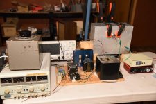
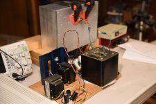
Finished assembling the test amplifier today. It is a very temporary setup. The SIT is just clamped to the heatsink. I have a fan below the heatsink to blow air up through the heatsink, in case the testing drags out.
The power supply is capable of 60V at 3A, and it has current limiting capabilities so hopefully it will keep me out of trouble. I have a series of power resistors for the source bias which I can adjust as well.
I'll double check the wiring tomorrow and do some tests.
The power supply is capable of 60V at 3A, and it has current limiting capabilities so hopefully it will keep me out of trouble. I have a series of power resistors for the source bias which I can adjust as well.
I'll double check the wiring tomorrow and do some tests.
Attachments
What a glorious test setup! Can't wait to see how this circuit performs.
I've been eyeing the J&K Tango FG-50S rendition for a while now. Are these the ones that we're seeing above?
https://jandkaudiodesign.blogspot.com/2014/11/solid-state-output-transformer.html?m=1
I've been eyeing the J&K Tango FG-50S rendition for a while now. Are these the ones that we're seeing above?
https://jandkaudiodesign.blogspot.com/2014/11/solid-state-output-transformer.html?m=1
I had a late start today, so I didn't get a lot done. After checking the wiring and doing some preliminary measurements on the voltage amplifier stage, I powered up the output stage and started live testing with a 1kHz signal on input and an 8 ohm resistor on output.
I gradually applied voltage to the output stage while monitoring the current through the 2SK182ES. I was also watching the signal at various circuit points with the oscilloscope. Everything was normal, which made me very happy. I got up to 30V to the 2SK182ES with a current of 1.44A. With resistance of output transformer and source resistors of about 3 ohms, this results in a Vds of about 25V.
30V is the limit of one side of my power supply, and being late, I didn't want to series the other 30V for higher voltages, so I headed straight for a listening test. I wired up my test speaker and a boom-box CD player and let her rip. No obvious issues were heard. My test speaker uses an Altec Lansing 511 horn / compression driver on the top end with a 12 inch woofer in a ported box, so I could crank it up a bit. The top end was decent. I was concerned about high frequency roll-off, but it was not evident from listening. Measurements will tell the true story.
I think this transformer coupled SIT idea will work. Tomorrow, I'll rig up the power supply for 50V to the 2SK182ES, run some measurements and do some more listening.
I powered up the 2SK182ES with the lab power supply in series mode today. This, in theory, is capable of 60V at 3A. I measured the output distortion at 1 watt with various combinations of operating points and transformer loading. I also reconfigured the amp and tried it out in common source mode.
In the end, the lowest distortion was achieved with the original design of voltage amplifier / source follower. It is the schematic in post #44 with the addition of a bypass capacitor paralleling the 2SK182ES source resistor. The resulting distortion is not as low as predicted by LTSpice. It is about 0.6% at 1 watt. I thought it would be lower than this. However, common source mode with the transformer loading the drain (without voltage amplifier) did produce higher distortion as expected.
I could not determine distortion at higher power output as my lab power supply began current limiting when I started increasing the input signal. I will have to build a power supply to test the higher power outputs. I wonder what effects, if any, the lab power supply had on the test results.
I did manage to clean up the noise picked up by the transformers by repositioning the choke for the voltage amp power supply.
I listened to some music with the amp, and it does sound nice. After about an hour of listening, the lab power shut down. I think it was due to high temperatures. I was able to restart it after a period of cooling, so nothing was damaged.
Attachments
- Home
- Amplifiers
- Pass Labs
- Look, Ma, No Coupling Caps! A Transformer Coupled VFET/SIT Amp Design