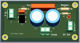
Been there, done that with the 5-pin capacitor footprint. The fun part was doing the infill white silkscreen for the negative polarity semi-circle.
One Kicad tip - for connection to the fills, as long as the pads and the fill have the same net name, they will be connected. There is no need to double up with the traces.
One Kicad tip - for connection to the fills, as long as the pads and the fill have the same net name, they will be connected. There is no need to double up with the traces.
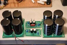
I have the voltage amplifier power supply PCB design completed. The power supply will be CLC filtered, not that an inductor is necessary, but I have some laying around and it is time to use up some of my stuff. Snubber components are also onboard. It is negative voltage out for the 2SJ28 so the ground is positive.
Attachments
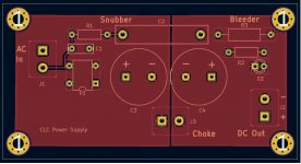
You're right, Ben. I just used the default settings of KiCad and checking on that, the track width is 0.25mm. I guess, working on the screen with the image larger than life, I didn't realize how tiny that is. In reality, though, the tracks are probably sufficient since the output current will be less than 100mA and the transformer is 120V:120V. According to the KiCad calculator, an 1oz copper, 0.25mm wide track by 20mm long for a 10C temperature rise, is good for about 0.9A.
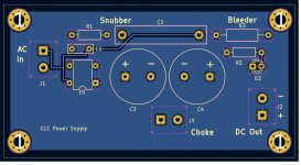
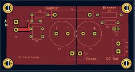
I have increased the width to 0.5mm and that is good for over 1.4A. I don't need extra fuses on the PCB.
I have increased the width to 0.5mm and that is good for over 1.4A. I don't need extra fuses on the PCB.
1 mm trace width =approx= 40 milli-inches trace width == 40 mils is a nice compromise for through hole boards, in areas where the components aren't tightly packed together. 3 mm for high current traces that aren't part of a plane or "copper flood", 0.4 mm when you need to weasel a trace between IC pins.
_
_
Attachments

Last edited:

I've been busy doing other things, but finally I'm back to this project. I ordered and received my power supply circuit boards and pretty well have all the parts needed.
The amplifiers will consist of a dual mono power supply in its own case and then each amplifier channel will be monoblocks. Each monoblock will be built in the style of tube amplifiers with exposed components mounted on a top plate which will sit on a wooden support base.
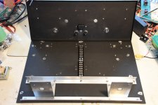
For the power supply, I bought a steel rackmount case. The sheet metal base plate is quite flexible so I reinforced it with aluminum angles to support the weight of the toroid power transformers. Once the side and back panels are attached, the overall case should be rigid enough. The load in the centre of the base plate will be quite low. There are some chokes but they will be along the sides. The transformers and PCBs for the voltage amp stages will be mounted on the back panel.
All the holes have been drilled for the case except for the on/off switches and LEDs holes in the front panel, but those will be easy to do. So, all the dirty work is done for the power supply.
The amplifiers will consist of a dual mono power supply in its own case and then each amplifier channel will be monoblocks. Each monoblock will be built in the style of tube amplifiers with exposed components mounted on a top plate which will sit on a wooden support base.
For the power supply, I bought a steel rackmount case. The sheet metal base plate is quite flexible so I reinforced it with aluminum angles to support the weight of the toroid power transformers. Once the side and back panels are attached, the overall case should be rigid enough. The load in the centre of the base plate will be quite low. There are some chokes but they will be along the sides. The transformers and PCBs for the voltage amp stages will be mounted on the back panel.
All the holes have been drilled for the case except for the on/off switches and LEDs holes in the front panel, but those will be easy to do. So, all the dirty work is done for the power supply.
Attachments

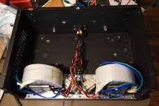
The power supply is getting closer to the finish line. I have wired the line/primary circuitry and populated the circuit boards for the front end and output stage. I ran some tests on the boards and there were no surprises.
Ordered and received the aluminum top plates for the amplifiers, so the project is approaching critical mass.
Ordered and received the aluminum top plates for the amplifiers, so the project is approaching critical mass.
Attachments
The power supply is finished. In the end, there was not as much excess space as I thought there would be. I bought the case and then designed the circuit boards without even thinking whether everything would all fit in the case. Being cheap, I tried to make the PCBs as small as possible, and I just got lucky that everything did fit inside the case.
Attachments
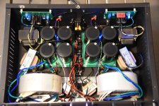

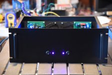
When I was looking for connectors a few months ago, I had difficulty finding ones that were 4 pole, could handle high DC voltage, and were in stock somewhere. So, this is what I ended up with. Would not have been my first choice, but they should work.
Solid work! In my business it’s better to be lucky than good any day 😂The power supply is finished. In the end, there was not as much excess space as I thought there would be. I bought the case and then designed the circuit boards without even thinking whether everything would all fit in the case. Being cheap, I tried to make the PCBs as small as possible, and I just got lucky that everything did fit inside the case.
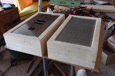
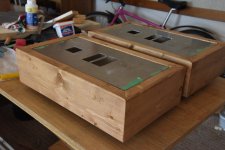
Now, I'm onto the mono amplifiers. The amps will be built in a style that is popular with tube amps. The major components will be mounted on a top plate which will sit on a wooden base. I'm using 9 inch x 18 inch by 1/8 inch aluminum plates.
So far, I've finished all the major hole cutting. I was dreading it, but it went quicker than I thought it would. I spent more time laying it out than actually doing the drilling and cutting. Only small holes left to be drilled. That's the easy stuff.
I'm going with fan cooling of the 2SK182ES in order to keep the heatsinks small. The fans will be Noctua computer types running on low voltage. I used Noctuas on my BAF2015 THF-51S amps and at low voltage, I can't hear them. I will suspend them under the top plate to blow air up through the heatsink. I bought perforated aluminum plates for the bottom of the amps, so there will be no restrictions on the air flow.
Attachments


Lots of things to do now that spring is here, so my amp building progress is not very speedy. However, I have made progress.
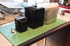
I tested my heatsink/fan cooling system using the actual heatsink and fan combo that I'm planning to use. The heatsinks are from a Yamaha B1 that I got for free and the fans are Noctua NF-R8 redux 1200. The fans are rated at moving 35.8 cubic metres of air per hour at 12V, 35mA.
I clamped an 8 ohm power resistor to the heatsink and applied 24V, 3A to it. I had originally hoped that I could run the fans at less than rated speed, but in the end, I went with the 12V power. This kept the heatsink at about 50 degrees centigrade. A 90mm fan would be better, but I'll keep these fans for now. In the amps, I'll feed them with the SIT 60V power supply with a dropping resistor and zener diode.
During the last couple of days, I mostly completed building the wood bases for the amps. I figured it would be a lot easier working on the amps if I had a cradle to hold the top plate. Being cheap, I used 2x6 framing studs (1.5 inches x 5.5 inches). These are not fine furniture material, but with some wood filler and sanding, and then stained, they will be presentable.
Now, I can get onto curve matching some SITs and slinging solder.
Attachments
depending of actual controler in fans itself, don't be surprised if they spray some nasty noise, if you use same power circuit with amp
I had case of exactly that, on one of my T-Beds, where even using LM317 properly filtered didn't help
in the end I mounted small xformer just to feed nasty fan, instead of further messing with chokes yadayada
I had case of exactly that, on one of my T-Beds, where even using LM317 properly filtered didn't help
in the end I mounted small xformer just to feed nasty fan, instead of further messing with chokes yadayada
The heatsinks are from a Yamaha B1 that I got for free
 Gotta be a good story there…
I'll check the power line with my oscilloscope to see what's present. Hopefully, some RC stages and decoupling will keep the noise down.
Yep, good story on the heatsinks. I thought I had found the Holy Grail when I saw an ad for 2SK77s at a good price. The seller said his technician had checked them out and they were good. I sent money; he sent a pair of 2SK77s on heatsinks. I couldn't believe my luck.
When I received them, I did the usual SIT tests (diode, resistance), and they failed spectacularly. After much back and forth, the seller refunded my money and told me I could keep the parts.
Apparently his technician did not understand SITs, and I was under the influence of SIT fever as I didn't ask for specific details about his test procedures until later.
So, now I have two nice heatsinks and two dead 2SK77s. At least my amps will have Yamaha B1 heatsinks.
I stained the wood bases and applied one coat of Minwax Tung Oil. The look not too bad. I'd say they have the rustic look. Should look fine at midnight when listening to music, after a drink.
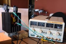
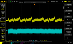
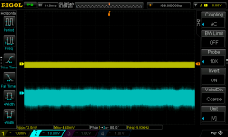
Heeding Zen Mod's warning about using the amp power supply for the cooling fan, I rigged up a test to see how bad it would be if I took that approach. I dialed my lab power supply to 19V, added a 330 ohm series dropping resistor and then 0.22 uF and 12000uF filter/decoupling capacitors, and a 12V zener across the fan motor terminals. There is about 160mVpp of noise at the fan terminals (yellow trace), but no sign of that noise at the input to the dropping resistor (power supply output, blue trace). I confirmed that by disconnecting the fan and checking the power supply output.
So, it looks like I may be lucky with these Noctua DC fans. In my actual implementation, the power supply will be 60V so I hope the larger series dropping resistor will result in even better filtering. Fingers crossed.
Attachments
- Home
- Amplifiers
- Pass Labs
- Look, Ma, No Coupling Caps! A Transformer Coupled VFET/SIT Amp Design